Theory
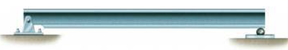
Beams are referred to members that support loadings applied perpendicular to their longitudinal axis [1]. A beam is considered statically determinate if the external reaction forces can be calculated using equations of static equilibrium.

Figure 1: Beam Type Examples that are Statically Determinate [1].
If the beams external reaction forces cannot be computed using equations of static equilibrium, it is considered statically indeterminate. The number of external reaction forces in excess to the equations of static equilibrium equations is called the degree of static indeterminacy. On figure 2, there are two beam configurations: on the left, the beam has one pin support (two reaction forces) and one roller support (one reaction force) which gives us a total of three external reaction forces. On the right, the beam has one pin support (two reaction forces) and three roller supports (three reaction forces) which gives us a total of five external reaction forces.The beam on the left is considered statically determinate and can be solved with equations of static equilibrium while the beam on the right is statically indeterminate and requires other methods of analysis.
- Equations of Equilibrium = 3
- # of Unknown External Reaction Forces = 3
- ∴ Statically Determinate
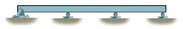
- Equations of Equilibrium = 3
- # of Unknown External Reaction Forces = 5
- ∴ Statically Indeterminate to the 2nd Degree
Figure 2: Statically Determinate vs. Statically Indeterminate Beam.
Majority of structures in real world applications are statically indeterminate. Solving statically indeterminate beams manually is a tedious and time-consuming task. With the use of computer-automation, it is possible to analyze complex statically indeterminate beams using the Matrix Stiffness Method.
Matrix Stiffness Method:
The Matrix Stiffness Method, also known as the Direct Stiffness Method, is an implementation of the Finite Element Method.This method uses the beam stiffness relationships to calculate member forces and displacements. The method is applied by modelling the beam structure into simpler elements interconnected at the nodes.The stiffness matrix for each element is compiled into a single global stiffness matrix which demonstrates the behavior of the beam structure [2].
The stiffness matrix for each beam element is shown below:

Where,
E = modulus of elasticity of the element,
I = moment of inertia of the element,
L = length of the element
For more information about how this stiffness matrix was developed, refer to the appendix.
The unknown displacements and forces can then be solved using equation 1 below:
F=K x D (eq.1) [2]
Where,
F = vector of the beam’s forces,
K = beam’s stiffness matrix,
D = vector of the beam’s displacements
Graphical Representation:
When designing beams, it is important to determine the variations of internal shear, internal moment, slope, deflection, bending stress, and shear stress along its span to find the points where the values are maximum, these values govern the design. An example of a shear and moment diagram is shown on figure 3.

Figure 3: Shear and Moment Diagram for a Simply Supported Beam [6].
By implementing the Matrix Stiffness Method, the external support reaction forces and displacements are calculated for the beam, this provides us with all the information needed to construct the diagrams that will aid in the beam design process. To plot the required diagrams, a graphical method is used that considers differential relations that exist between loading, shear, moment, slope, and deflection.

Where,
V = shear; M = moment; Φ = slope; s = deflection
As an example of the relationships discussed, the area under the shear diagram between any two points is equal to the change in moment between the two points, this is shown in the figure 4.

Figure 4: Relationship between Shear and Moment [1].