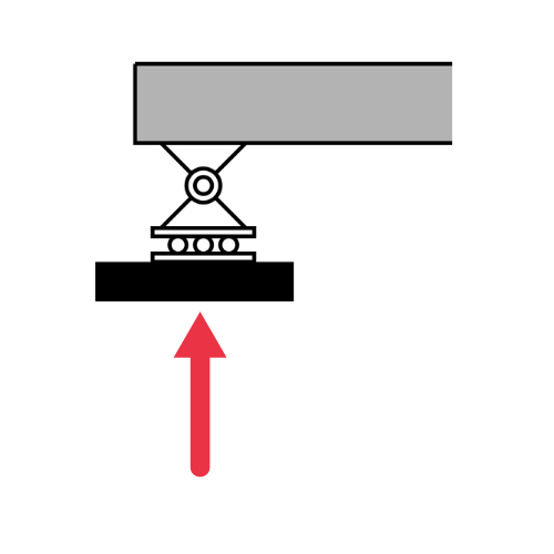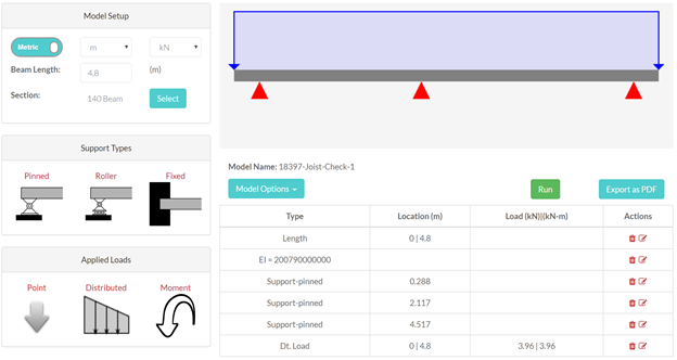
Simply supported beam
Pin at one end, roller at the other
A simply supported beam is supported at two points, commonly with a pin at one end and a roller at the other. The supports allow rotation, so the beam does not develop fixed-end moments at the supports.
Support model
Pin + rollerWhat to read from the figure
Vertical reactions
Loads resolve into RA and RB at the two supports.
Free rotation
The ends can rotate, so ideal end moments are zero.
Single span
L is measured between the pin and roller centerlines.
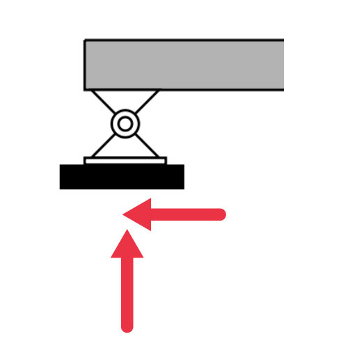
Support reactions
For a vertical loading case, a simply supported beam typically has a vertical reaction at each support. If one support is pinned, it can also resist horizontal force. For symmetrical loading, the two vertical reactions are often equal.
Common uses and loads
Simply supported beams are common in floors, roofs, bridges, lintels and basic framing members. Common loading examples include a point load at midspan, a uniform distributed load across the full span, or several point loads from joists or secondary beams.
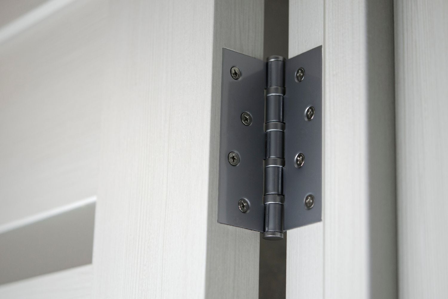
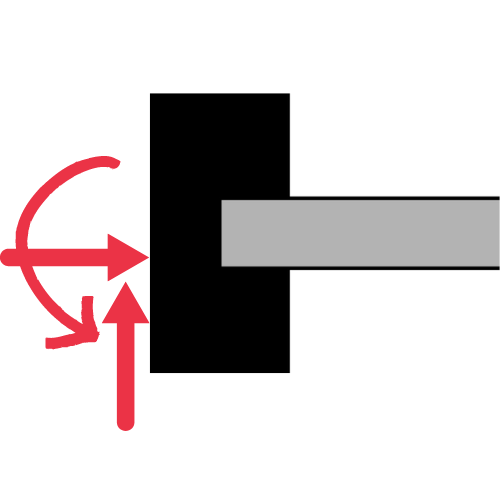
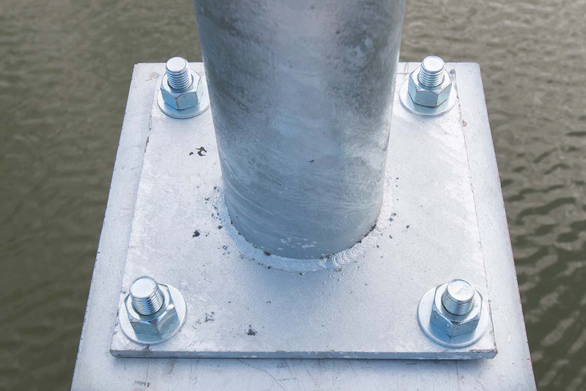
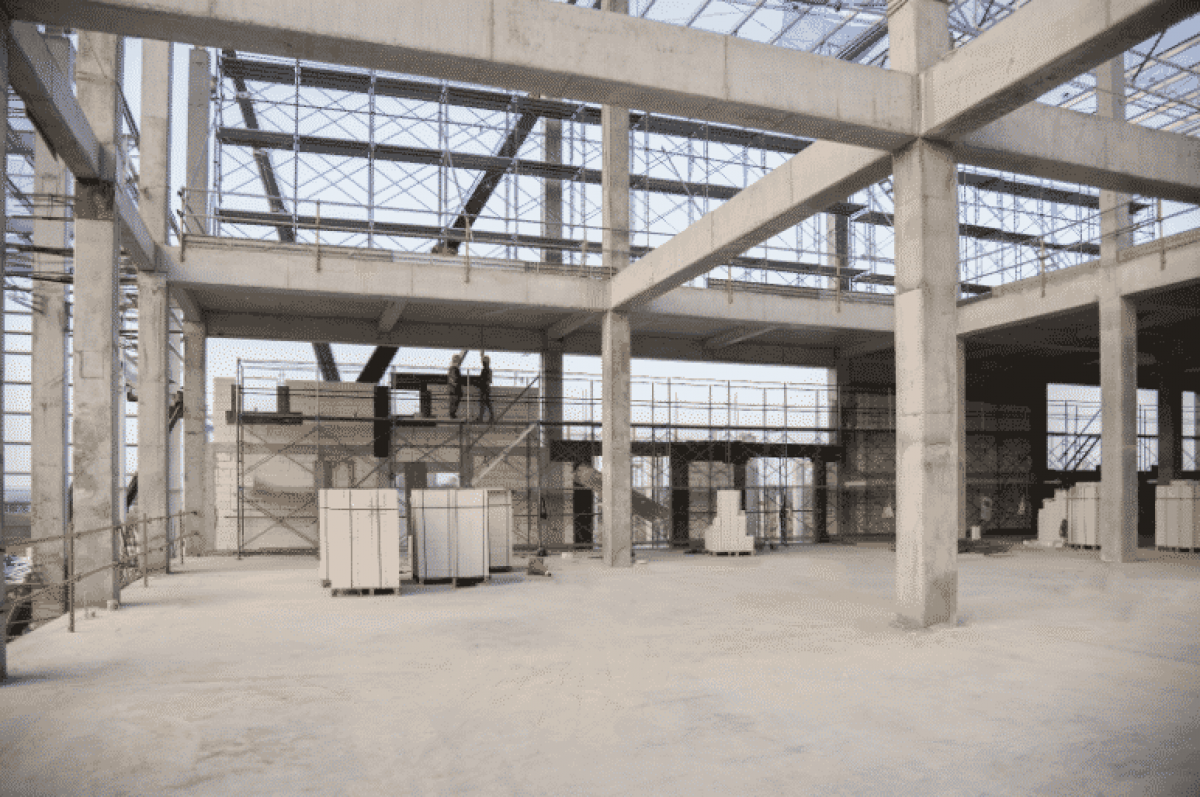
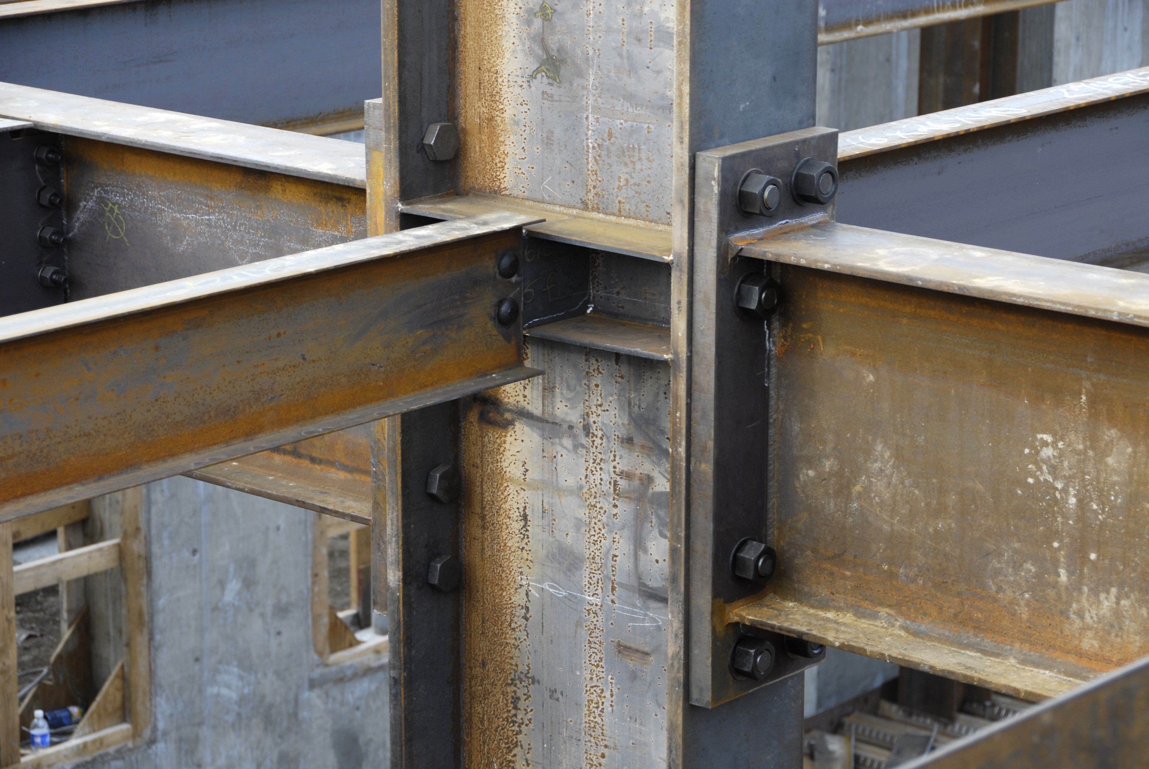
In real life
Simply supported beam IRL
In real life, a simply supported beam is any beam that spans between two bearing points and is free to rotate at its supports, so the supports carry vertical (and sometimes horizontal) reactions but no end moments. Real connections often have some rotational stiffness, so engineers use the simply supported model whenever end rotation is close enough to the ideal pin-and-roller assumption.
- Floor joist on bearing walls
- Steel beam, shear-tab connection
- Bridge girder on bearings
- Lintel over an opening
- Roof purlin between frames
Center point load
Symmetric point load placed at x = L/2.
- Support reactions
- RA = RB = P / 2
- Maximum moment
- Mmax = PL / 4 at midspan
- Maximum deflection
- δmax = PL3 / 48EI at midspan
Full-span UDL
Uniform load w applied continuously from A to B.
- Support reactions
- RA = RB = wL / 2
- Maximum moment
- Mmax = wL2 / 8 at midspan
- Maximum deflection
- δmax = 5wL4 / 384EI at midspan