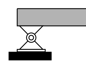
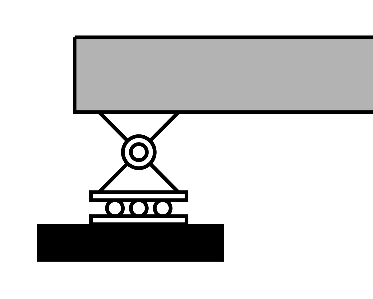



Simply supported
Center point load
6 m span with a 30 kN point load at midspan.
- Pinned and roller supports
- Equal support reactions
- Peak moment at midspan
Analyze simply supported, cantilever, fixed and continuous beams online. Calculate reactions, shear force, bending moment, slope, deflection and stress diagrams.
Review supports, loads and section properties before running.
Beam length, supports, and applied loads
| Type | Location (m) | Load (kN)|(kN-m) | Actions |
|---|
Cross-sections and material properties along the beam
| Beam Section | Location (m) | Properties | Actions |
|---|
Working with connected members?
Use the 2D Structural Analysis app for portal frames, trusses, braced frames and mixed connected systems, with reactions, displacements and member axial, shear and bending results.
Example model shortcuts
Choose a preset to load the calculator with supports, loads and section values already filled in. It is the fastest way to explore results before building a custom model.
Simply supported
6 m span with a 30 kN point load at midspan.
Simply supported
6 m span with a 10 kN/m uniform distributed load.
Cantilever
3 m cantilever with a 10 kN load at the free end.
Fixed beam
6 m fixed-ended beam with a 10 kN/m uniform load.
Continuous
Two equal spans with a continuous uniform load.
Overhanging
6 m supported span plus a 2 m loaded overhang.
Beam calculator guide
Use the sections below to understand what the calculator solves, how each output should be read, and how steel sections, I-beams, section properties, stress results and PDF reports fit into the same beam analysis model.
What this beam calculator solves
Optimal Beam can be used as a beam reaction calculator, shear force diagram calculator, bending moment diagram calculator, beam deflection calculator and beam stress calculator in one workflow. Define the span, supports, loads and section properties, then run the model to generate the diagrams and values used for engineering review.
Instead of limiting the workflow to one beam type, the calculator supports common single-span cases, cantilever beams, simply supported beams, continuous beams, indeterminate beams, standard steel sections and custom section properties on the same page.
Calculate vertical reactions and fixed-end moments based on the support restraints in the model.
Generate shear force and bending moment diagrams to identify maximum shear, maximum bending moment and critical locations.
Use modulus of elasticity and moment of inertia to review how the beam rotates and deflects under the applied loads.
Review bending stress and average shear stress when section properties and material stiffness are included.
Workflow
Build the beam model in the calculator above, run the analysis, then review the support reactions, shear force diagram, bending moment diagram, deflection, stress results and PDF report options.
Enter the beam length and choose metric or imperial units.
Add pinned, roller or fixed supports at their exact locations along the beam.
Add point loads, distributed loads or applied moments with their magnitudes and positions.
Select a standard steel section, I-beam or custom section properties when deflection or stress results are needed.
Run the model to calculate support reactions, shear force diagrams, bending moment diagrams, slope, deflection and stress results.
Save the model or export a PDF calculation report when the beam analysis needs to be documented or shared.
Beam types
The support layout defines the beam type. Use pinned, roller and fixed supports to model common beam conditions, from simply supported and cantilever beams to fixed, overhanging and continuous beams. After running the model, review reactions, shear diagrams, bending moment diagrams, deflection and stress results for the selected support condition. Span length is one of the main inputs because it affects reactions, bending moment and deflection.
| Beam type | How to model it | What to review |
|---|---|---|
| Simply supported | Add a pinned support at one end and a roller support at the other. | Support reactions, shear sign change, maximum bending moment and midspan deflection for symmetric loads. |
| Cantilever | Add a fixed support at one end and leave the other end free. | Fixed-end reaction, fixed-end moment, maximum bending moment and maximum deflection near the free end. |
| Fixed-fixed | Add fixed supports at both ends. | End moments, reduced deflection, support restraint effects and bending moment distribution. |
| Overhanging | Place one or more supports inside the beam length so part of the beam extends beyond a support. | Moment reversal near supports, reaction distribution and deflection at the overhanging end. |
| Continuous | Add three or more supports to create two or more spans. | Support moments, span moments, load redistribution and deflection across adjacent spans. |
Load types
Use the calculator as a beam load calculator by adding the loads that define the structural action on the beam. Point loads, distributed loads and applied moments can be combined in the same model to represent column reactions, floor loads, equipment loads, connection moments and other common loading conditions.
A concentrated force applied at a single location, such as a column reaction, hanger load, wheel load or equipment load.
A load spread over part or all of the span, such as floor load, roof load or self-weight. Use equal start and end values for a uniform load, or different values for a varying load.
A concentrated moment applied at a specific location along the beam, useful for idealized connection effects, rotational loads or load transfer cases.
Need to reconcile load units first? Use the point load converter for kN, kip and lb, the line load converter for kN/m, kip/ft, lb/ft and tributary loads, or the bending moment unit converter.
Shear and moment
After the beam model is run, Optimal Beam calculates support reactions and generates shear force and bending moment diagrams. These diagrams show how internal force demand changes along the beam span.
Point loads create jumps in the shear diagram, distributed loads change the slope of the shear diagram, and the shear diagram controls the slope of the bending moment diagram. That relationship is why a zero crossing in the shear diagram usually indicates a local maximum or minimum in the bending moment diagram. To compare results across unit systems, use the kN·m, kip·ft, lb·ft and lb·in bending moment converter.
Deflection
Beam deflection depends on span length, support condition, load type, material stiffness and section moment of inertia. A longer span or heavier load increases deflection, while a higher modulus of elasticity or larger moment of inertia reduces it.
Optimal Beam can calculate slope and deflection diagrams when section and material properties are included. You can assign standard sections, I-beams or custom section properties to the beam, including multiple cross-sections along different parts of the span to model changes in stiffness.
Span
Longer spans usually increase deflection significantly, especially under distributed loads.
Load
Point loads, distributed loads and applied moments create different deflected shapes.
Material
The modulus of elasticity E controls material stiffness and directly affects deflection.
Section
Moment of inertia I measures how strongly a section resists bending. Larger moment of inertia usually reduces deflection. Need section properties? Use the moment of inertia calculator.
Deflection and slope diagrams are available when section and material properties are included. Guests can view full deflection and stress diagrams on their first three manual runs and on imported examples; create a free account for ongoing access.
Steel and I-beams
Optimal Beam can analyze steel beams and I-beams by selecting standard steel sections, including common wide-flange shapes, or by entering custom section properties. The selected section properties feed directly into slope, deflection, bending stress and shear stress calculations.
Use this workflow for beam analysis, section comparison and preliminary engineering review. For final steel member sizing, code checks, bracing checks, capacity checks and connection design should be completed according to the applicable design standard by a qualified professional.
Although many users analyze steel beams and I-beams, the same workflow can be used with wood, aluminum or custom material properties by entering the appropriate modulus of elasticity and section properties.
| Input | Why it matters | Used for |
|---|---|---|
| E | Material stiffness, such as steel, aluminum, wood or a custom value. | Slope and deflection. |
| I | Moment of inertia about the bending axis. | Flexural stiffness and deflection. |
| A | Cross-sectional area of the beam section. | Average shear stress. |
| ytop, ybottom | Distance from the neutral axis to the top and bottom extreme fibers. | Bending stress at extreme fibers. |
Need section properties first? Use the section properties calculator for standard shapes, or the free custom and arbitrary cross-section builder to create a built-up section or import a DXF.
Stress
Stress results connect the internal force diagrams to the selected beam section. Bending stress comes from bending moment and section geometry, while average shear stress comes from shear force and section area.
Convert MPa, ksi, psi and kPa consistently before comparing stress demand or material values with the structural stress unit converter.
Bending stress
σ = M c / I
M = bending moment, c = distance to extreme fiber, I = moment of inertia
Use the bending moment, distance to the extreme fiber and moment of inertia to calculate normal stress from flexure.
Average shear stress
τavg = V / A
Use the shear force and section area to calculate average shear stress demand along the beam.
Stress results are useful for comparing sections and identifying critical locations along the beam. Final allowable stress, strength, code and capacity checks should be completed separately according to the applicable design standard.
Documentation
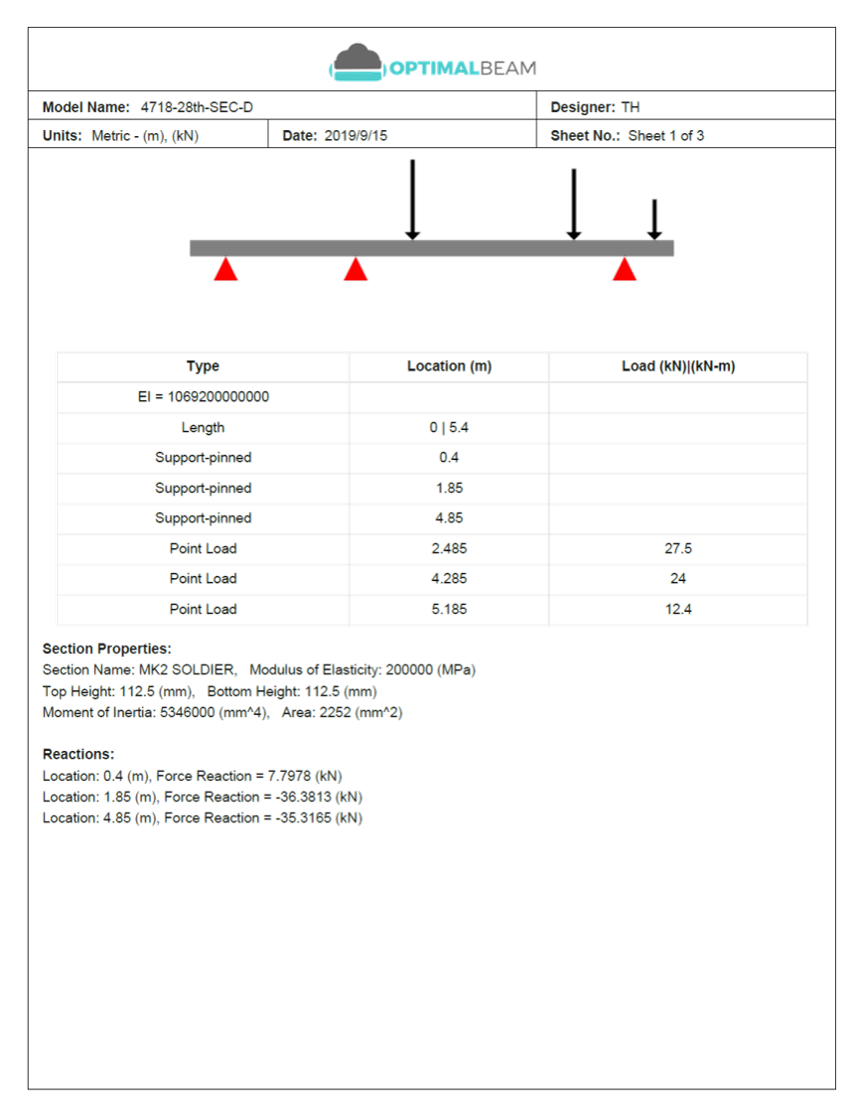
After you run a beam model, PDF Export turns the model inputs, reactions, diagrams and selected report details into a shareable calculation record. Use it for internal review, project files, client records or team handoff without collecting screenshots by hand.
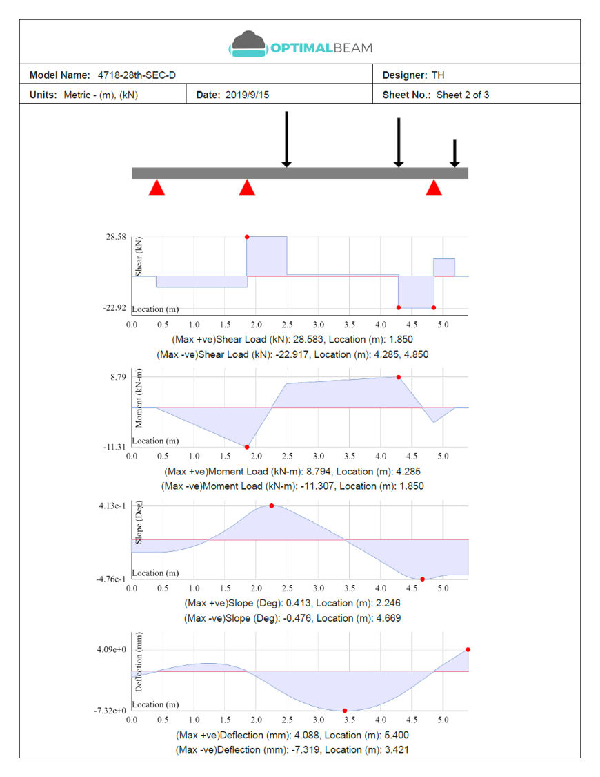
What the report can include
Worked checks
Use these worked beam examples to compare calculator output against common hand-check formulas. Start with simple support and load cases, then move to more complex beam models with multiple supports, sections and load combinations.
Example 1 · Simply supported UDL w
Full-span uniform load checked against the standard simply supported beam formulas.
Example 2 · Cantilever point load P
Tip load check showing the fixed support reaction, shear and negative support moment.
The shear diagram stays constant at 6 kN along the span, while the moment diagram grows linearly back to the fixed support. The deflection check should show the largest displacement at the free tip.
Method and assumptions
Optimal Beam is intended for beam analysis, diagram generation and engineering review workflows. Results depend on the geometry, supports, loads, section properties, material stiffness and units entered by the user.
The calculator uses idealized support conditions and beam models. Real connections, bearings, bracing, materials, load paths and construction details can behave differently from the ideal model.
Use this for
Beam analysis, load path review, diagram generation, section comparison and preliminary engineering review.
Requires professional review
Final member sizing, code compliance, span tables, bearing checks, bracing, connection design and construction decisions.
Want the technical background? Read the beam theory and matrix stiffness method documentation.
Questions and answers
Optimal Beam calculates support reactions, shear force diagrams, bending moment diagrams, slope, deflection, average shear stress and bending stress for beam models with supports, loads and section properties.
Yes. Optimal Beam can calculate slope and deflection diagrams when section and material properties are included. Deflection depends on span length, support conditions, loads, modulus of elasticity and moment of inertia.
Deflection and stress results use section properties such as modulus of elasticity E, moment of inertia I, area A, and distances to the top and bottom extreme fibers. Standard sections can be selected, or custom section properties can be entered.
Yes. You can assign different standard or custom sections to different parts of the beam span to model stepped beams, splices, repairs or stiffness changes.
Yes. Optimal Beam can analyze steel beams and I-beams by selecting standard steel sections or entering custom section properties. The calculator is useful for beam analysis, section comparison and preliminary engineering review.
Yes. The calculator supports common beam models including simply supported beams, cantilever beams, fixed beams, overhanging beams, continuous beams and statically indeterminate beams.
You can apply point loads, distributed loads and applied moments. Loads can be combined in the same model to represent common structural loading conditions.
Yes. PDF reports can include model inputs, supports, loads, reactions, section properties, shear force diagrams, bending moment diagrams, slope and deflection diagrams, stress results and selected report details.
The basic beam calculator is free to use. Guests can run full deflection and stress diagrams on three manual runs and on imported examples. Advanced features such as saved models, Optimal AI, PDF reports, saved custom sections and ongoing diagram access may require a trial or upgraded account.
No. Optimal Beam is intended for beam analysis, diagram generation, section comparison and engineering review workflows. Final member sizing, code compliance, bracing, bearing checks, connection design and construction decisions should be reviewed by a qualified professional.
The equal reactions and 20 kN maximum shear should match the ends of the shear force diagram. The parabolic bending moment diagram should peak at midspan, where the deflection curve also reaches its maximum sag.