Quick answer
What is a cantilever beam?
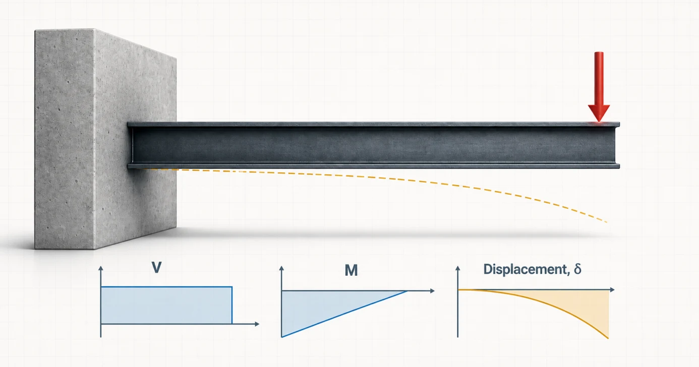
A cantilever beam is fixed against translation and rotation at one end and free at the other. Because there is no second support, the fixed end must resist the entire vertical load plus a fixing moment. For common downward loads, moment is largest at the support while deflection is largest at the free tip.
Read the model from left to right
Fixed end
Prevents movement and rotation; develops force and moment reactions.
Moment demand
Builds toward the support as the lever arm to the load increases.
Free tip
Has no support reaction and usually experiences the maximum displacement.
From structure to model
Where cantilever beams appear in real life
A cantilever is recognizable by its single load path back to a restrained support. The highlighted member in each scene projects beyond that support with no vertical support at its outer end.
Buildings
Cantilevered balcony
Idealized model
Fixed at the façade; free at the balcony edge.
- Why it fits
- A projecting slab or beam carries occupants and finishes back to the building line through bending and shear.
- Model with care
- A slab may bend in two directions, and the backspan, thermal bridge, torsion and façade connection can require a plate or frame model.
Entrances and façades
Column-free entrance canopy
Idealized model
Fixed at the building; free along the outer edge.
- Why it fits
- Gravity, snow and maintenance loads act along a projection whose support must provide vertical reaction and fixing moment.
- Model with care
- Hangers, knee braces or concealed posts change the system. Wind uplift can also reverse the bending direction and connection forces.
Transportation infrastructure
Traffic-signal mast arm
Idealized model
Fixed at the pole; free at the far signal.
- Why it fits
- The horizontal arm transfers signal weight and wind effects to one rigid pole connection, with demand building toward that joint.
- Model with care
- Pole flexibility, vibration, fatigue, torsion and multidirectional wind usually require a three-dimensional frame check beyond beam formulas.
Recognition rule: if a hidden hanger, bracket, post or bearing provides another load path, the member is not behaving as a pure cantilever.
Cantilever beam formulas
Deflection, reaction and moment formulas
The following closed-form equations use the cantilever length L, point load P, distributed load w, Young’s modulus E, second moment of area I, and flexural rigidity EI. Use one consistent unit system throughout.
| Load case | Schematic | Fixed-end shear | Max moment magnitude | Max deflection | Tip slope |
|---|---|---|---|---|---|
| Point load P at free tip |
|
VA = P | |MA| = PL | δmax = PL3 / 3EI | θB = PL2 / 2EI |
| Full-span UDL w |
|
VA = wL | |MA| = wL2 / 2 | δmax = wL4 / 8EI | θB = wL3 / 6EI |
| Point load P at x = a |
|
VA = P | |MA| = Pa | δtip = Pa2(3L − a) / 6EI | θtip = Pa2 / 2EI |
| Applied end moment M0 |
|
VA = 0 | |M| = M0 | δtip = M0L2 / 2EI | θtip = M0L / EI |
For multiple loads in a linear-elastic model, effects can be superimposed. The full beam calculator performs that combination and draws the complete response.
Need to compare this case with simple, fixed, overhanging or continuous supports? Browse the complete beam deflection formula library.
SFD and BMD
How the shear and bending moment diagrams change
How to read the plots: positive shear and sagging moment are above their baselines; negative values are below. The dashed orange line is the exaggerated deflected shape.
Point load at the free end
Constant shear, linear moment
- Shear: constant magnitude P between the tip and support.
- Moment: linear from zero at the free tip to −PL at the fixed end; |M|max = PL.
- Deflection: cubic curve with maximum PL3/(3EI) at the tip.
Full-span UDL
Linear shear, parabolic moment
- Shear: zero at the free tip and increases linearly to wL.
- Moment: parabolic from zero at the free tip to −wL2/2 at the fixed end; |M|max = wL2/2.
- Deflection: maximum wL4/(8EI) at the tip.
With the common sagging-positive convention, these downward loads produce negative (hogging) bending near the support. Some references plot cantilever moments on the opposite side of the baseline; compare magnitudes and verify the stated sign convention before treating a visual difference as a calculation error.
Worked examples
Two complete cantilever beam hand checks
Compare a concentrated tip load with a full-span distributed load. Each example carries the same 3.0 m beam from equilibrium through moment and deflection, using its own matching schematic and calculator model.
3 m span · 10 kN point load at the free tip
- Span
- L = 3.0 m
- Point load
- P = 10 kN
- Flexural stiffness
- E = 200 GPa, I = 100 × 106 mm4
EI = 20,000 kN·m2
1 · Vertical equilibrium
ΣFy = 0 → VA = P10 kN2 · Moment equilibrium about A
MA = −PL = −(10 × 3)−30 kN·m3 · Free-tip deflection
δB = PL3 / 3EI = 10(33) / [3(20,000)]4.50 mm4 · Serviceability ratio
L / δ = 3,000 / 4.50L/667The wall is the critical section: shear remains constant, moment grows linearly toward the fixed end, and the deflected shape reaches its largest value at the unsupported tip. L/667 is descriptive only—check the project’s actual serviceability criteria.
3 m span · 8 kN/m UDL over the full cantilever
- Span
- L = 3.0 m
- Uniform load
- w = 8 kN/m
- Flexural stiffness
- E = 200 GPa, I = 100 × 106 mm4
EI = 20,000 kN·m2
1 · Replace the UDL with its resultant
W = wL = 8 × 3; x = L/224 kN at 1.5 m2 · Vertical equilibrium
ΣFy = 0 → VA = W24 kN3 · Moment equilibrium about A
MA = −W(L/2) = −(24 × 1.5)−36 kN·m4 · Free-tip deflection
δB = wL4 / 8EI = 8(34) / [8(20,000)]4.05 mmA full-span UDL produces linear shear and a negative parabolic moment diagram, both largest at the wall. The 4.05 mm tip displacement is about L/741; apply the project’s actual strength, connection and serviceability criteria.
Real-world cantilevers
Examples, idealization and common mistakes
Balconies, canopies, awnings, sign arms, crane booms, retaining-wall stems and projecting roof members can behave as cantilevers. The useful question is not whether a member “looks like” an overhang, but whether one end supplies the rotational restraint and load path assumed by the model.
Use a cantilever model when
- One end provides meaningful translational and rotational restraint.
- The far end has no vertical support.
- The connection and backspan can transfer the calculated support moment.
- A constant-EI, small-deflection approximation is appropriate.
Do not hide these effects
- Connection rotation or semi-rigid fixity.
- Torsion from eccentric loading.
- Lateral-torsional buckling or local connection failure.
- Vibration, impact, fatigue, large deflection or changing section stiffness.
Five frequent calculation mistakes
- Measuring L to the wrong point. For a point load, the lever arm is measured from the support restraint to the load application point.
- Using total UDL as the intensity. w is force per length; the resultant is wL and acts at L/2.
- Mixing mm and m inside EI. Keep force and length units consistent before applying a deflection formula.
- Looking for maximum moment at the tip. The ordinary unloaded free tip has zero bending moment; the fixed end governs.
- Checking the member but not the restraint. The support connection and anchorage must actually transfer VA and MA.
Boundary conditions matter
Cantilever vs. simply supported beam
| Question | Cantilever | Simply supported |
|---|---|---|
| Restraint | One fixed end, one free end | Usually pin + roller |
| Support moment | Required at fixed end | Zero in the ideal pin/roller model |
| Classic point-load max moment | PL at fixed end | PL/4 at midspan |
| Classic point-load max deflection | PL3/3EI at tip | PL3/48EI at midspan |
Those point-load rows compare a cantilever tip load with a simply supported central point load. They are useful for understanding restraint, not interchangeable design cases. Read the simply supported beam calculator and formula guide for the pin–roller model.
Engineering basis
Assumptions and limits of the formulas
- Beam theory: Euler–Bernoulli bending.
- Geometry: straight, slender, prismatic member.
- Material: homogeneous, linear elastic E.
- Response: static loading and small deflection.
- Stiffness: constant EI unless modeled otherwise.
- Not included: code design, buckling, connection design or dynamic response.
Formula consistency and the checking process are documented in the sources and verification section below. Results are educational analysis outputs, not a substitute for project-specific design and review by a qualified engineer.
Sources and verification
Reference basis and checking process
The equations are classical, closed-form Euler–Bernoulli beam solutions. Coefficients and boundary-condition behavior for the cantilever tip-load, eccentric point-load, applied-moment and full-span UDL cases were checked against the references below before the worked values were published.
Closed-form references
- American Wood Council, Beam Design Formulas with Shear and Moment Diagrams (DA 6) Reference configurations, reactions, shear, bending moment and elastic-deflection coefficients.
- University of Illinois Mechanics Reference, Beam Deflection Moment–curvature integration, Euler–Bernoulli assumptions and displacement boundary conditions.
How the examples were checked
Each expected value was recalculated from the displayed equation and checked against force and moment equilibrium where applicable. The worked-example links carry the same geometry, stiffness and loading into the calculator so the response diagrams can be compared with the hand check.
Review the published solver verification methodologyThese checks verify the stated idealized analysis cases; they do not constitute design certification or replace project-specific review of loading, restraints, stability, connections and governing requirements.
Frequently asked questions
Cantilever beam questions
What is the cantilever beam deflection formula for a point load at the free end?
For a prismatic cantilever in linear-elastic, small-deflection bending, the maximum deflection at the free tip is delta = PL^3/(3EI). P is the tip load, L is the cantilever length, E is Young’s modulus and I is the second moment of area.
Where are maximum moment and maximum deflection on a cantilever beam?
For the usual downward point-load and distributed-load cases, the maximum bending-moment magnitude is at the fixed support and the maximum vertical deflection is at the free tip.
What are the reactions for a cantilever with a tip point load?
A downward tip load P produces an equal upward shear reaction P and a fixing moment PL at the built-in support. The horizontal reaction is zero when no horizontal load is present.
What are the formulas for a cantilever beam under a full-span UDL?
For a full-span uniformly distributed load w, the fixed-end shear is wL, the fixed-end moment magnitude is wL^2/2, and the free-tip deflection is wL^4/(8EI).
Why does a cantilever deflect more than a simply supported beam?
A cantilever carries load through one fixed end while its other end is free. For the classic equal-span, equal-EI point-load comparison, PL^3/(3EI) is sixteen times the central-point-load deflection PL^3/(48EI) of a simply supported beam.
What is the difference between a cantilever and a propped cantilever?
A pure cantilever has one fixed end and one unsupported free end, so it is statically determinate. A propped cantilever adds a simple support near the free end, making the beam statically indeterminate and redistributing reaction, moment and deflection.
How far can a cantilever beam span?
There is no universal cantilever span limit. The usable projection depends on loading, EI, strength, stability, vibration, connection and backspan capacity, allowable deflection and the applicable code and project criteria.
When should I use the full beam calculator instead of the quick calculator?
Use the full calculator for multiple or partial loads, point loads away from the tip, applied moments, nonstandard support positions, custom sections, mixed units, or when you need complete downloadable diagrams and results.