Quick answer
What is a continuous beam?
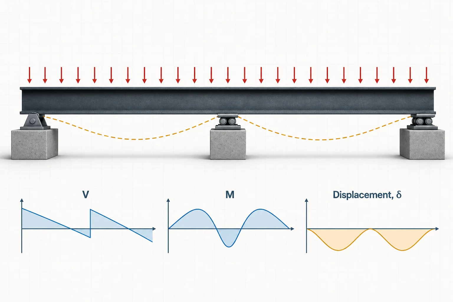
A continuous beam passes over more than two supports. This reference model has two equal spans ℓ, exterior supports A and C, and interior support B. Its total length is 2ℓ.
Continuity prevents the two spans from rotating independently at B. That compatibility creates a negative bending moment over the interior support, redistributes reactions, and usually reduces positive span moment and deflection compared with two disconnected simple beams.
What makes the beam continuous
Exterior supports
A and C have zero ideal support moment but non-zero rotation.
Interior support B
Vertical displacement is zero while the uncut beam carries negative moment through the support.
Compatibility
The slope from span AB must match the slope from span BC at B.
From structure to model
Where continuous beams appear in real life
A beam is continuous when the same uncut member passes across an interior support. That continuity transfers bending through the support and couples the response of adjacent spans.
Bridges
Multi-span bridge girder
Idealized model
One girder passing over an interior pier between end supports.
- Why it fits
- Continuity over the pier creates negative support moment and reduces positive span moment under balanced gravity loading.
- Model with care
- Unequal spans, bearing arrangement, deck composite action, moving vehicles, temperature, settlement and construction sequence affect redistribution.
Multi-bay buildings
Floor beam over several columns
Idealized model
Unspliced beam continuous across an interior column.
- Why it fits
- The neighboring bays share rotation at the column, so loading one bay changes reactions and bending in the others.
- Model with care
- Moment connections, slab composite action, column stiffness and beam splices can make the system a frame rather than a simple-support continuous beam.
Industrial roofs
Roof purlin across multiple frames
Idealized model
One purlin lapped or continuous over successive rafters.
- Why it fits
- The member crosses intermediate supports without a hinge, developing hogging moment above frames and sagging moment between them.
- Model with care
- Lap details, lateral restraint, uplift, section slenderness and unequal frame spacing must match the assumed continuity and stiffness.
Recognition rule: adjacent members touching at a support are not automatically continuous. Moment must be able to pass through the splice or uncut section for the spans to interact.
Two-span continuous beam formulas
Reactions, interior moment and maximum deflection
These coefficients apply only to two equal spans ℓ, constant EI, level simple supports and the exact load patterns shown. Negative moment is hogging; positive moment is sagging.
| Load case | Schematic | Support reactions | Interior moment | Maximum positive moment | Maximum deflection |
|---|---|---|---|---|---|
| UDL w on both spans |
|
RA = RC = 3wℓ/8 RB = 5wℓ/4 | MB = −wℓ2/8 | M+max = 9wℓ2/128 at 3ℓ/8 from A or C | δmax ≈ wℓ4/(184.63EI) at 0.4215ℓ |
| P at center of span AB only |
|
RA = 13P/32 RB = 11P/16 RC = −3P/32 | MB = −3Pℓ/32 | M+max = 13Pℓ/64 under P | δmax ≈ 0.015012Pℓ3/EI in span AB |
Equilibrium checks: for the balanced UDL, 3wℓ/8 + 5wℓ/4 + 3wℓ/8 = 2wℓ. For the one-span point load, 13P/32 + 11P/16 − 3P/32 = P. Equilibrium verifies the total reactions; compatibility is what determines their distribution and MB.
Comparing support systems or looking for V(x), M(x), slope and elastic-curve equations? Use the complete beam deflection formula library.
Continuous beam SFD and BMD
Balanced loading vs. one loaded span
The balanced case is symmetric. Loading one span breaks that symmetry, changes every reaction and can produce uplift at the remote exterior support.
How to read the plots: positive shear and sagging moment are above their baselines; negative values are below. The dashed orange line is the exaggerated deflected shape.
UDL on both equal spans
Balanced loading
The same uniform load w acts from A through B to C.
- Reactions: equal at A and C; B carries 5wℓ/4.
- Moment: −wℓ²/8 at B and +9wℓ²/128 in each span.
- Deflection: equal downward peaks at 0.4215ℓ from the ends.
Midspan point load on span AB
Unbalanced loading
P acts at the center of the left span while span BC is unloaded.
- Reactions: R_C = −3P/32, so the far support requires uplift restraint.
- Moment: positive under P and negative over B.
- Deflection: span AB sags while unloaded span BC lifts between supports.
Worked calculations
Two complete two-span continuous beam examples
Both examples use two 4 m spans and constant EI. The first is symmetric; the second shows why load patterning matters.
Two 4 m spans with 10 kN/m on both
Total length 8 m · supports at x = 0, 4 and 8 m
- Each span
- ℓ = 4 m each
- Uniform load
- w = 10 kN/m
- Input
- total load = 80 kN
- Elastic modulus
- E = 200 GPa
- Second moment of area
- I = 100 × 106 mm4
1 · Three-moment compatibility
MB = −wℓ2/8 = −10(42)/8−20.0 kN·m2 · Support reactions
RA = RC = 3wℓ/8; RB = 5wℓ/415, 50, 15 kN3 · Positive span moment
M+max = 9wℓ2/128 at 3ℓ/8+11.25 kN·m at 1.50 m4 · Maximum deflection
δmax ≈ wℓ4/(184.63EI)0.69 mmThe interior reaction is the largest and the negative support moment governs over the positive span moment. Reaction equilibrium closes exactly: 15 + 50 + 15 = 80 kN.
30 kN at the center of span AB only
Same two 4 m spans; span BC carries no applied load
- Each span
- ℓ = 4 m each
- Point load
- P = 30 kN at x = 2 m
- Elastic modulus
- E = 200 GPa
- Second moment of area
- I = 100 × 106 mm4
- Input
- span BC unloaded
1 · Interior support moment
MB = −3Pℓ/32 = −3(30)(4)/32−11.25 kN·m2 · Three reactions
RA = 13P/32; RB = 11P/16; RC = −3P/3212.19, 20.63, −2.81 kN3 · Moment under P
M+max = 13Pℓ/64+24.38 kN·m4 · Maximum displacement
max |y(x)| from the piecewise elastic curve1.44 mm at x ≈ 1.92 mPattern loading more than doubles the positive moment relative to Example 1 and lifts support C by 2.81 kN. Continuous-beam design must consider realistic load arrangements, not only every span fully loaded.
Practical multi-span modeling
When is the two-equal-span model appropriate?
Continuous beams are common in multi-bay floors, bridge girders, roof purlins, continuous slabs and members passing over columns or walls. The equal-span formulas are useful for checks, but real systems often have unequal spans, different stiffnesses and patterned loads.
Need the moment of inertia for a nonstandard profile? Use the free custom and arbitrary cross-section properties calculator for built-up geometry, polygons and DXF imports.
Good candidates
- Two equal spans with the same constant EI.
- Level simple supports with no imposed settlement.
- UDL on both spans or one center point load on span AB.
- Linear-elastic preliminary analysis and solver verification.
Use the full solver when
- Spans are unequal or there are more than two spans.
- Loads are partial, mixed, moving or patterned differently.
- EI varies by span, cracking changes stiffness or supports settle.
- Ends are fixed, supports are springs, or geometric/material nonlinearity matters.
Five frequent calculation mistakes
- Using total length in a per-span formula. Here ℓ is one span; the full beam length is 2ℓ.
- Trying to solve three reactions with equilibrium alone. Compatibility and EI are required.
- Forgetting the negative moment at B. The beam is continuous through the support even though B is drawn as a roller.
- Assuming every span is always fully loaded. Pattern loading can increase positive moment and create uplift.
- Using equal-span coefficients for unequal spans. Reactions and moments redistribute with geometry and stiffness.
System comparison
Continuous beam vs. separate simply supported spans
| Question | Continuous over B | Two separate simple beams |
|---|---|---|
| Member continuity | Uncut member passes across B | A hinge or physical break separates spans |
| Moment at B | Normally negative under gravity load | Zero at each simple end |
| UDL positive moment | 9wℓ²/128 in each span | wℓ²/8 in each span |
| UDL deflection | ≈ wℓ⁴/184.63EI | 5wℓ⁴/384EI |
| Reaction solution | Equilibrium + compatibility | Equilibrium alone |
Continuity reduces the balanced-load positive span moment and deflection, but it introduces negative support moment and makes results sensitive to span stiffness, settlement and load pattern.
Engineering basis
Assumptions and limits of the formulas
- Beam theory: Euler–Bernoulli bending.
- Geometry: two equal spans ℓ with total length 2ℓ.
- Supports: level simple supports at A, B and C.
- Stiffness: the same constant EI in both spans.
- Response: static, linear elastic and small deflection.
- Not included: settlement, springs, unequal spans, nonlinear cracking, buckling or dynamics.
The equal-span coefficients and 0.4215ℓ deflection location were cross-checked against American Wood Council Design Aid 6. The one-span point-load case was independently derived with the three-moment theorem and checked by equilibrium and the full calculator import.
Sources and verification
Reference basis and checking process
The equations are classical, closed-form Euler–Bernoulli beam solutions. Coefficients and boundary-condition behavior for the two-equal-span continuous-beam balanced and pattern-loaded cases were checked against the references below before the worked values were published.
Closed-form references
- American Wood Council, Beam Design Formulas with Shear and Moment Diagrams (DA 6) Reference configurations, reactions, shear, bending moment and elastic-deflection coefficients.
- University of Illinois Mechanics Reference, Beam Deflection Moment–curvature integration, Euler–Bernoulli assumptions and displacement boundary conditions.
How the examples were checked
Each expected value was recalculated from the displayed equation and checked against force and moment equilibrium where applicable. The worked-example links carry the same geometry, stiffness and loading into the calculator so the response diagrams can be compared with the hand check.
Review the published solver verification methodologyThese checks verify the stated idealized analysis cases; they do not constitute design certification or replace project-specific review of loading, restraints, stability, connections and governing requirements.
Frequently asked questions
Continuous beam questions
What is a continuous beam?
A continuous beam extends across more than two supports. The interior supports make the beam statically indeterminate and create negative support moments under common gravity loads.
What is the center support moment for two equal spans under UDL?
For equal spans ℓ, constant EI and the same UDL w on both spans, the interior support moment is MB = -wℓ^2/8.
What are the reactions for two equal continuous spans under UDL?
With UDL w on both equal spans ℓ, RA = RC = 3wℓ/8 and RB = 5wℓ/4. Their sum is 2wℓ, the total applied load.
Where is maximum positive moment for two equal spans under UDL?
It occurs 3ℓ/8 from each exterior support and equals 9wℓ^2/128. The interior support moment is negative and has the larger magnitude.
What is the maximum deflection for a two-span continuous beam under UDL?
For two equal spans with UDL on both, maximum downward deflection in each span is approximately wℓ^4/(184.63EI), located 0.4215ℓ from the exterior support.
Why can a continuous beam reaction be negative?
An unbalanced load pattern can lift an unloaded exterior support. For a point load at the center of only the left span in this equal-span model, RC = -3P/32.
Can equilibrium alone solve a continuous beam?
No. There are more reaction unknowns than independent equilibrium equations, so the analysis also needs compatibility of displacement and member stiffness.
When should I use the full continuous beam calculator?
Use it for unequal spans, more than two spans, mixed or partial loads, varying EI, support settlement, springs, fixed supports or any nonstandard support location.