Browser-based structural analysis

Beam Calculator first. Full 2D as your model grows.

Analyze supports, loads, reactions, shear, moment, deflection and stress in a focused beam workspace. When your model becomes a frame or truss, continue in the full 2D analysis workspace.

Core beam analysis is free. No installation required. Compare plans

Optimal Beam Model Analyze Verify Report
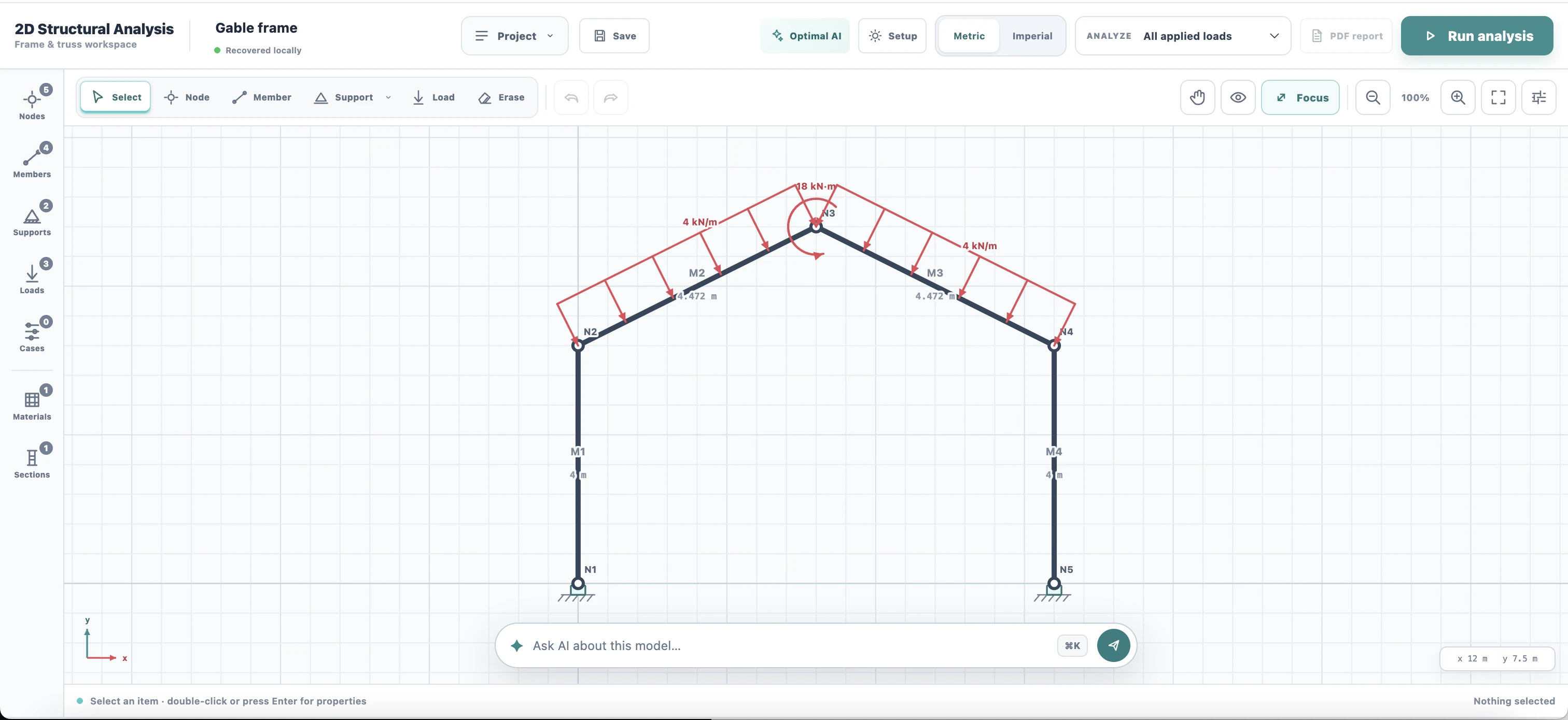
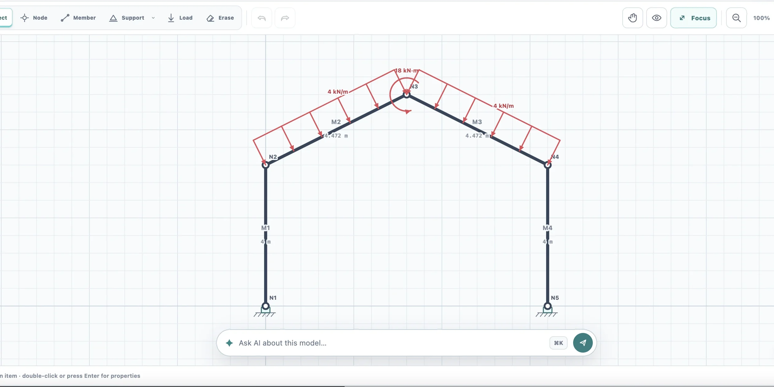
Optimal Beam 2D workspace showing a complete gable frame, supports and distributed roof loads
2 · Continue in 2D Frames & trusses
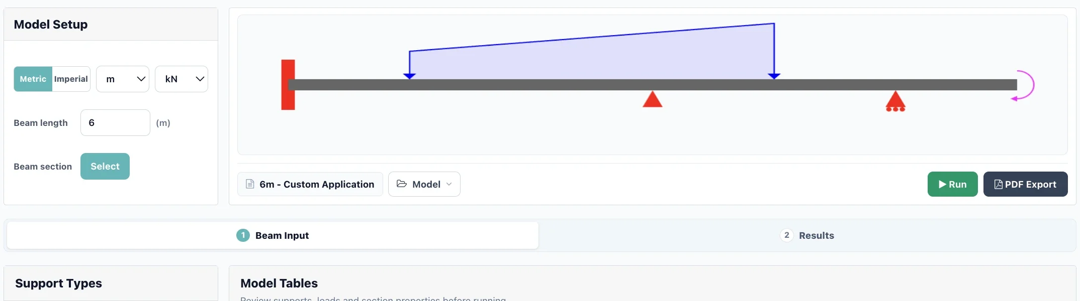
Optimal Beam calculator showing beam setup, applied loading and supports
1 · Start with a beam Beam Calculator

Workflow

A clear workflow from model to report

01

Build the modelDraw members, supports, and loads, then assign section and material properties.

02

Analyze the responseReview reactions, deflected shape, and axial, shear, and moment diagrams.

03

Document the calculationExport the model, assumptions, and detailed results to a professional PDF report.

Proven in practice

Trusted by engineers around the world

Engineers use Optimal Beam for quick checks, structural modelling, and clear, documented calculations.

Registered members
48,686
Beam analyses completed
1,492,273

Online beam analysis

Free online beam calculator for reactions, shear, moment, deflection and stress

Optimal Beam is built for fast, focused beam analysis. Model simply supported, cantilever, fixed, overhanging, continuous, and statically indeterminate beams in a purpose-built one-dimensional workspace.

Model the beam precisely

Place pinned, roller, and fixed supports with point loads, distributed loads, and applied moments at exact locations.

Review the complete response

See maximum and minimum values with their locations, then enter any position along the span to calculate shear, moment, slope, deflection, or stress at that point.

Assign section and material properties

Use custom or standard steel sections across one or more beam segments.

Export the calculation

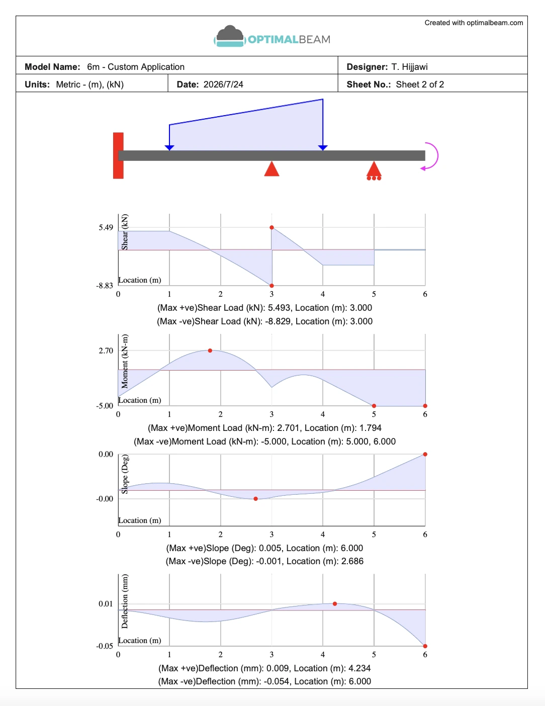
Choose which response diagrams to include, add the designer name, and carry the analyzed beam into a clear PDF calculation report.

PDF calculation report Shear · moment · slope · deflection
Optimal Beam PDF calculation report with the analyzed beam plus shear, moment, slope and deflection diagrams

Two purpose-built workspaces

Choose the right workspace for your model

Use the Beam Calculator for focused one-dimensional analysis. Move to 2D Structural Analysis when members connect into frames or trusses.

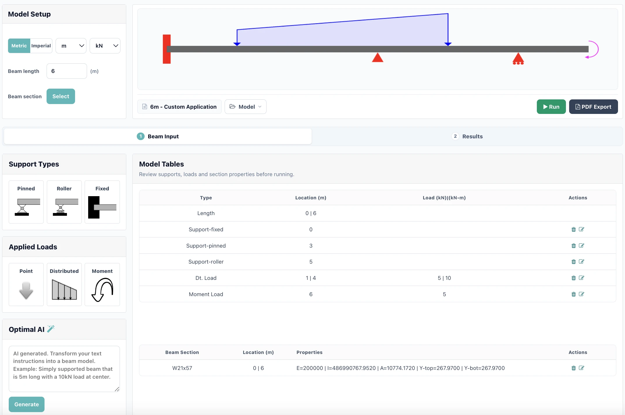
Optimal Beam Calculator workspace showing beam setup, supports, loading and model tables
Beam model setup

Focused one-dimensional analysis

Core analysis free

Beam Calculator

Set the span and stiffness, place pinned, roller or fixed supports at exact locations, then add point loads, distributed loads and applied moments along the beam.

  • Determinate and indeterminate beams
  • Support reactions
  • Shear and moment diagrams
  • Slope and deflection
  • Bending and shear stress
  • Saved models and PDF reports
Use the Beam Calculator
2D Structural Analysis workspace showing a gable frame with supports, distributed roof loads and an applied moment
2D frame workspace

Plane frame and truss analysis

Frames + trusses

2D Structural Analysis

Create nodes and members on the grid, assign supports and member-end releases, apply nodal or member loads, and solve stable determinate or indeterminate 2D models.

  • First-order direct stiffness solver
  • Frame and pin-ended members
  • Reactions and displacements
  • Axial, shear and moment
  • Cases, combinations and self-weight
  • Member-level charts and reports
Build a 2D model

Optimal AI · model-aware proposals

Professional feature

Ask for the change. Review it before it reaches your model.

Optimal AI works with the model already on screen. It turns your instruction into structured model operations, then pauses for review. Nothing changes until you approve it.

01

Describe the change

Tell Optimal AI how the current model should be modified

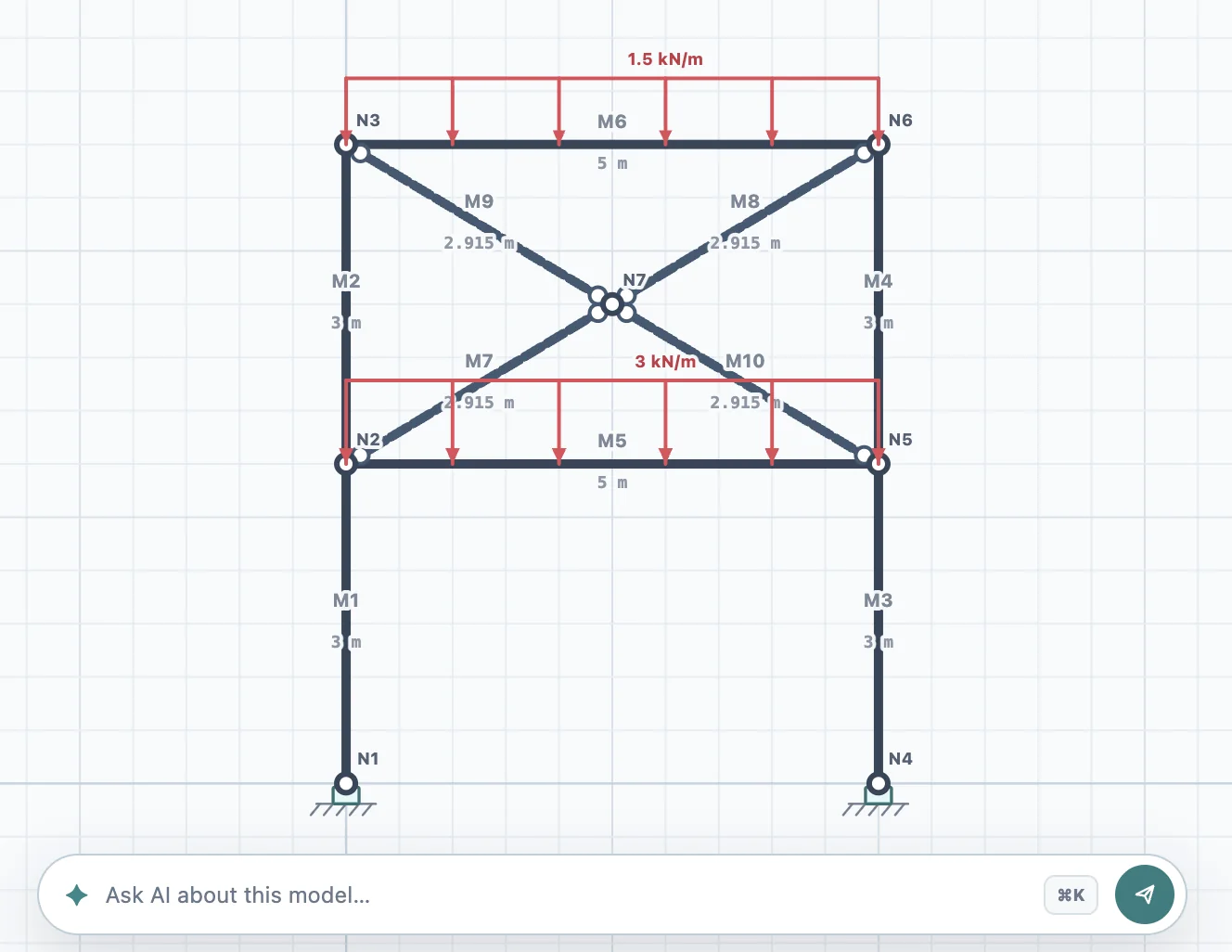
Existing braced two-storey frame before an Optimal AI model change request

The current geometry, assignments, model health, active selection and visible results provide the assistant’s working context.

02

Review before applying

Inspect the updated geometry and every proposed model operation

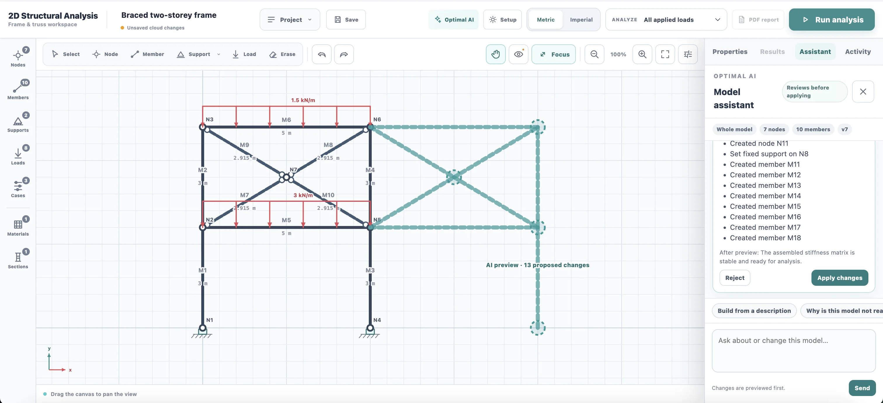
Optimal AI preview showing a proposed second braced bay, thirteen proposed model changes and Apply changes or Reject controls
Preview only 13 proposed changes
Existing model remains unchanged
Model operations Not a generated picture

Nodes, members, supports, loads, materials, and sections are proposed through the calculator’s existing modelling system.

Version-aware review The proposal stays tied to your model

When the model changes, an earlier proposal becomes outdated and cannot be applied to the newer version.

Deterministic analysis The structural solver calculates the results

Optimal AI assists with modelling and interpretation. Reactions, forces, and displacements are calculated by the structural solver.

The example above uses the actual braced-frame model and its real 13-change preview—not a conceptual illustration.

Explore Optimal AI

The data behind the model

Set up the model before you solve

Choose familiar units, assign the material and section properties the solver needs, and organize loading into cases and combinations.

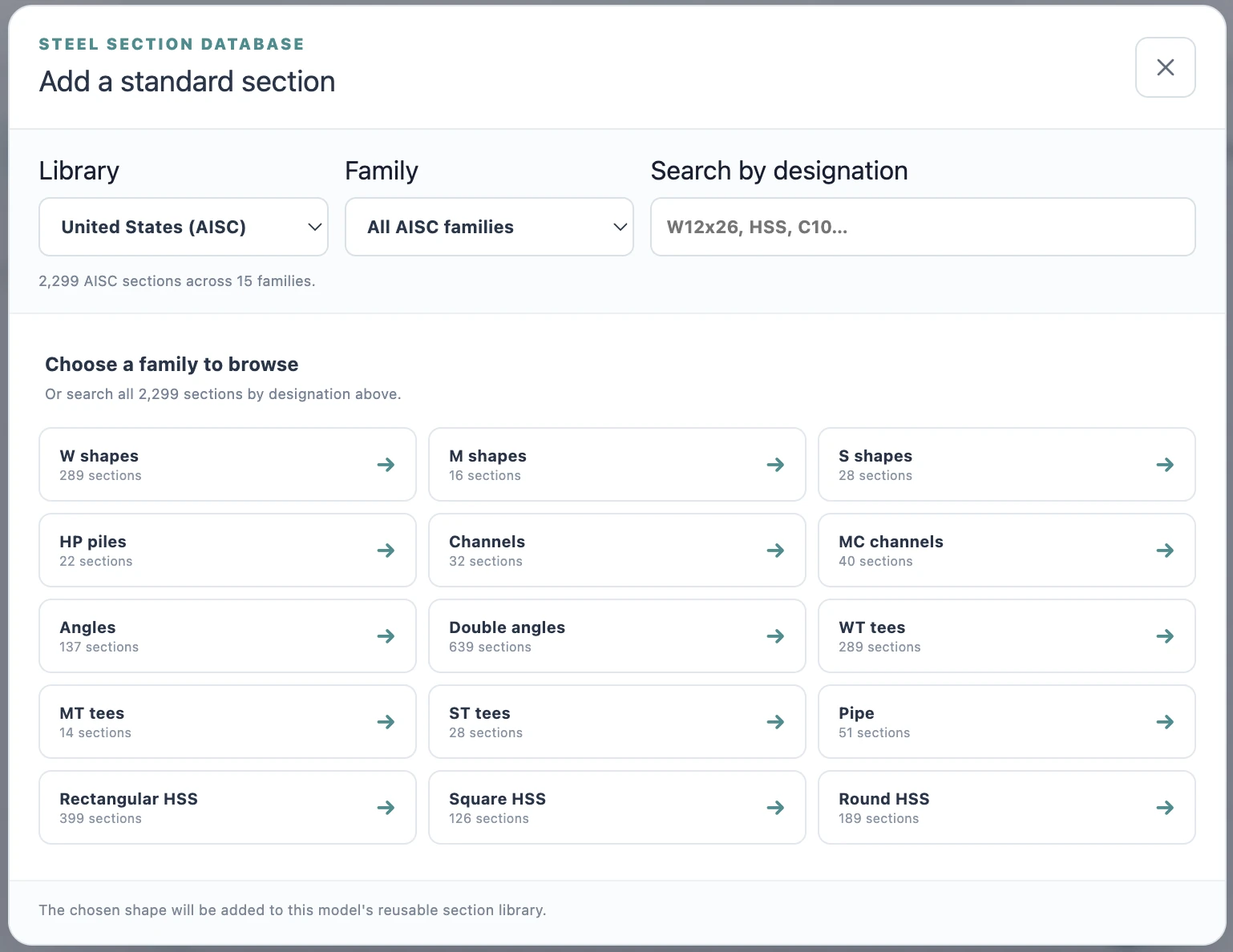
Optimal Beam steel section database showing the AISC library, section families and designation search

Units, sections and materials

Use the units, materials, and sections your work requires

Metric Imperial Convert the existing model

Switch units without rebuilding

Move between metric and imperial while converting the existing model inputs.

Use standard or custom sections

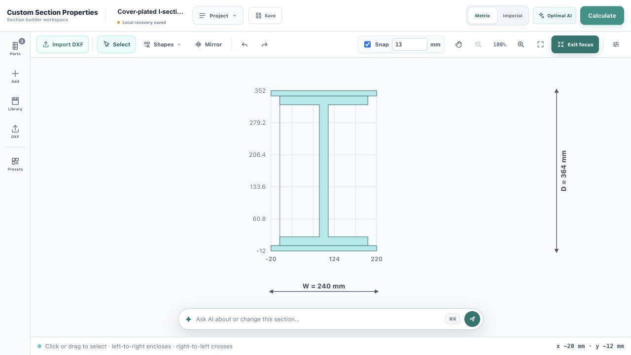
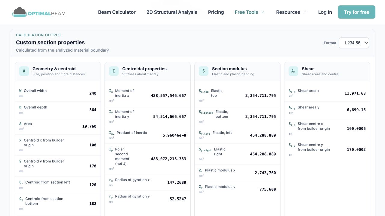
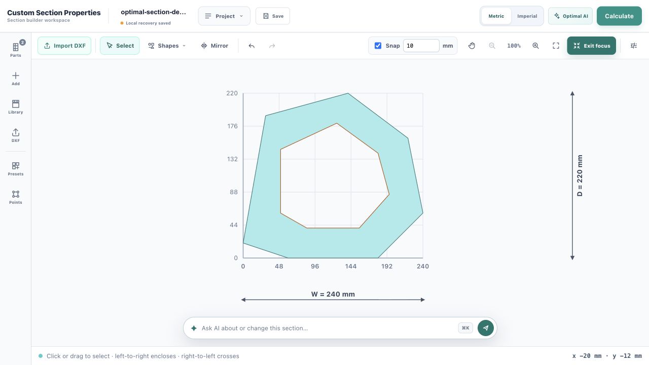
Choose from regional steel-section libraries or define your own cross-section and material properties.

Save and reuse sections

Assign different sections along the model and reuse saved custom properties in future studies.

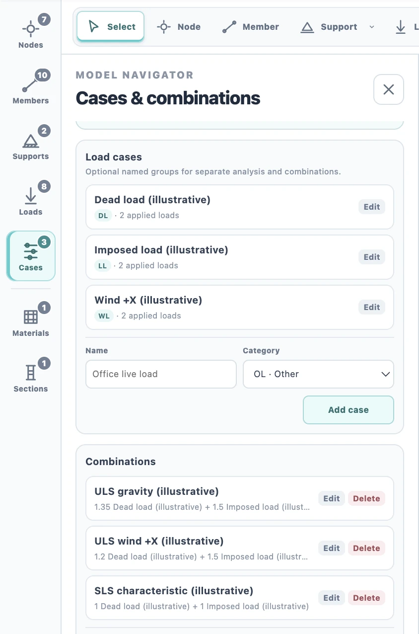
Optimal Beam load case and combination navigator showing named dead, imposed and wind cases plus ULS and SLS combinations

Load cases & combinations

Organize loads into named cases and combinations

Leave loads unassigned for a quick study, or group them into named load cases. Create linear combinations with custom factors, choose the scenario to solve, and carry it through every result view and report.

Inspect the calculated response

See how the structure responds—and where

The result is not reduced to a single maximum. Review the global response, select individual nodes or members, and trace peak values back to their location in the model.

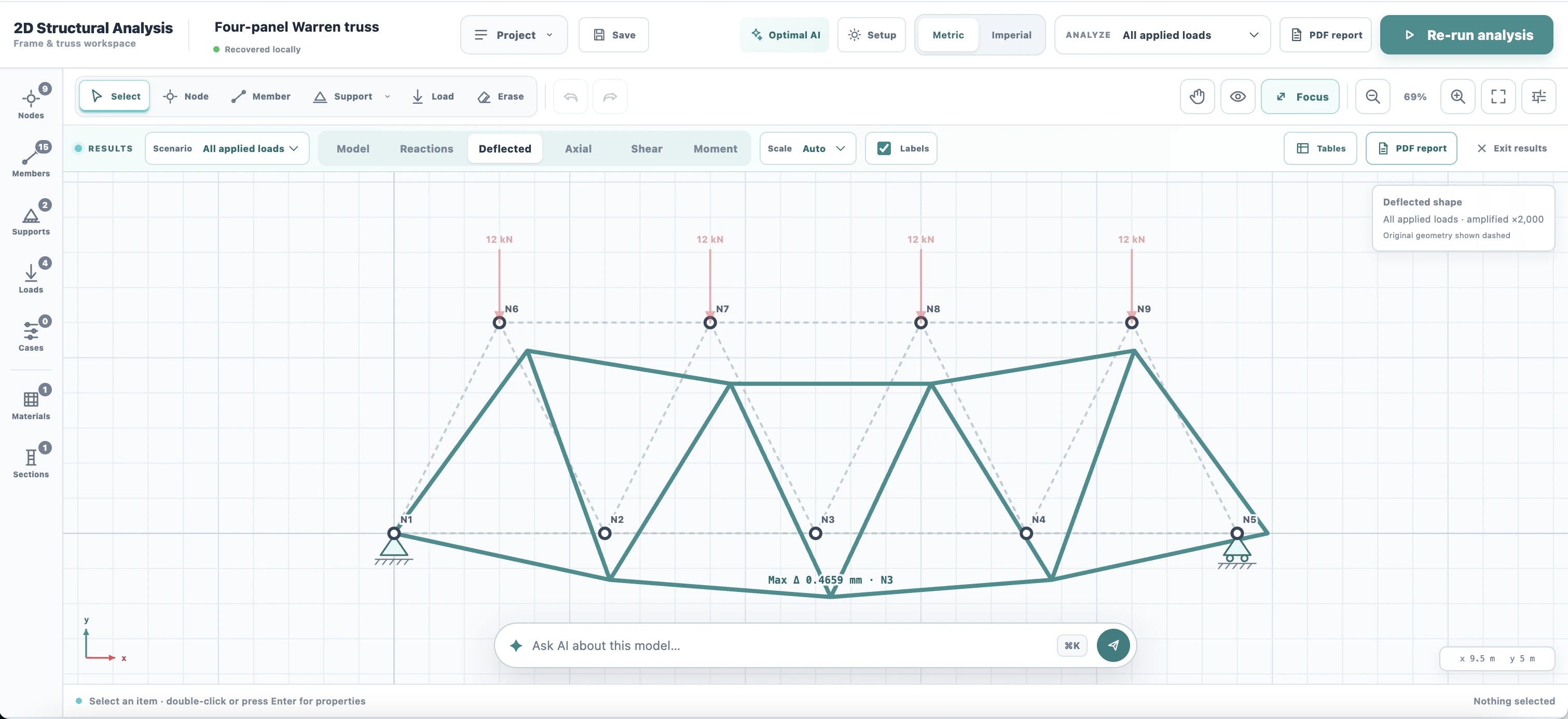
Four-panel Warren truss in Optimal Beam with original geometry dashed and the amplified deflected shape shown in teal
Deflected-shape result · Four-panel Warren truss

Global model results

Move between reactions, deflected shape, and force diagrams

Use one results ribbon to switch between the undeformed model, support reactions, amplified deflected shape, axial force, shear force, and bending moment. Control labels and the visual scale without changing the calculated values.

  • Original geometry remains visible as a reference.
  • Peak-result labels identify the controlling member or node.
  • The active load case or combination remains attached to the result view.
Example shown Four 12 kN nodal loads Maximum displacement: 0.4659 mm at N3
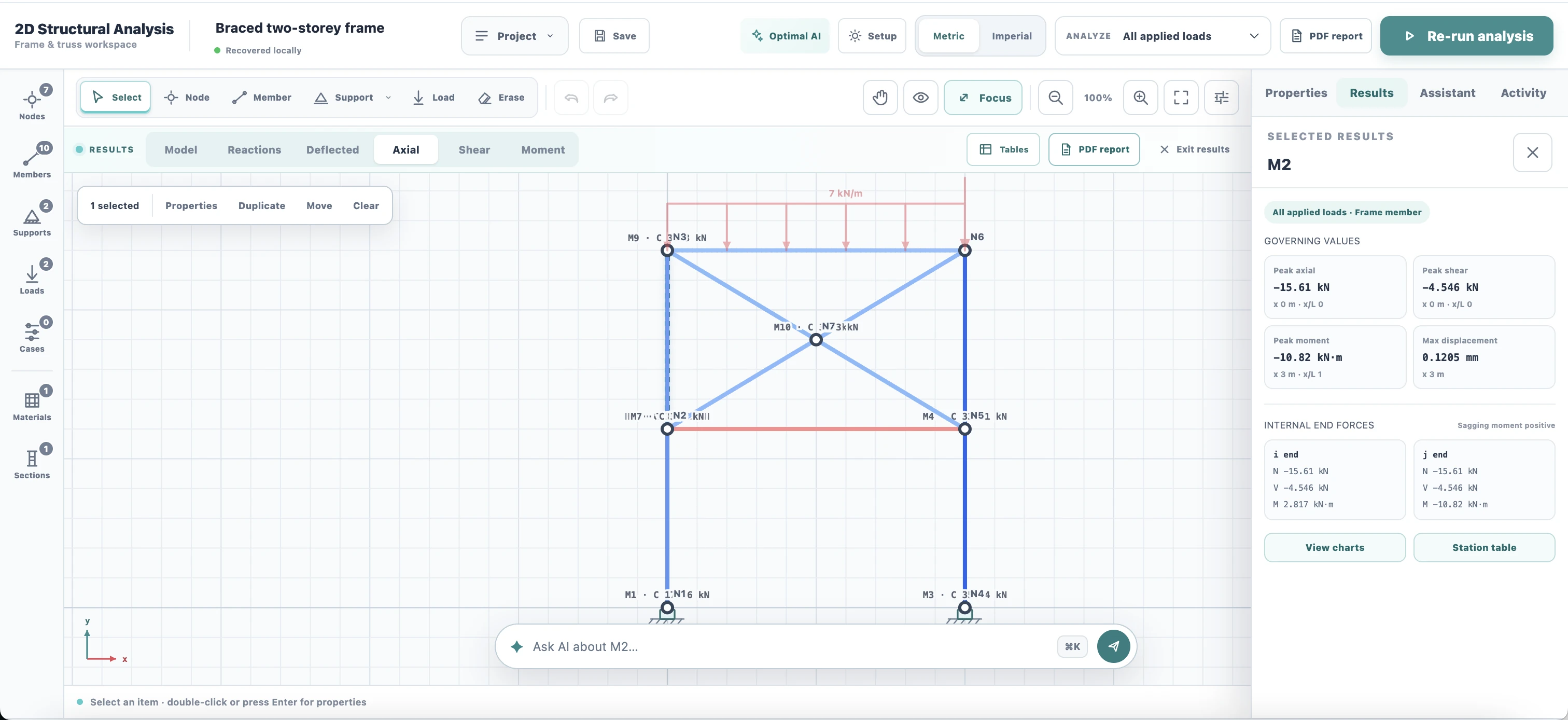
Optimal Beam 2D workspace with a selected frame member, peak result values and the model-aware AI prompt

Selection-aware review

Inspect a member without losing the model context

Select a member to see peak axial force, shear, moment, displacement, and local end actions beside the structure. Open detailed charts or station tables when you need a closer look.

Open member results
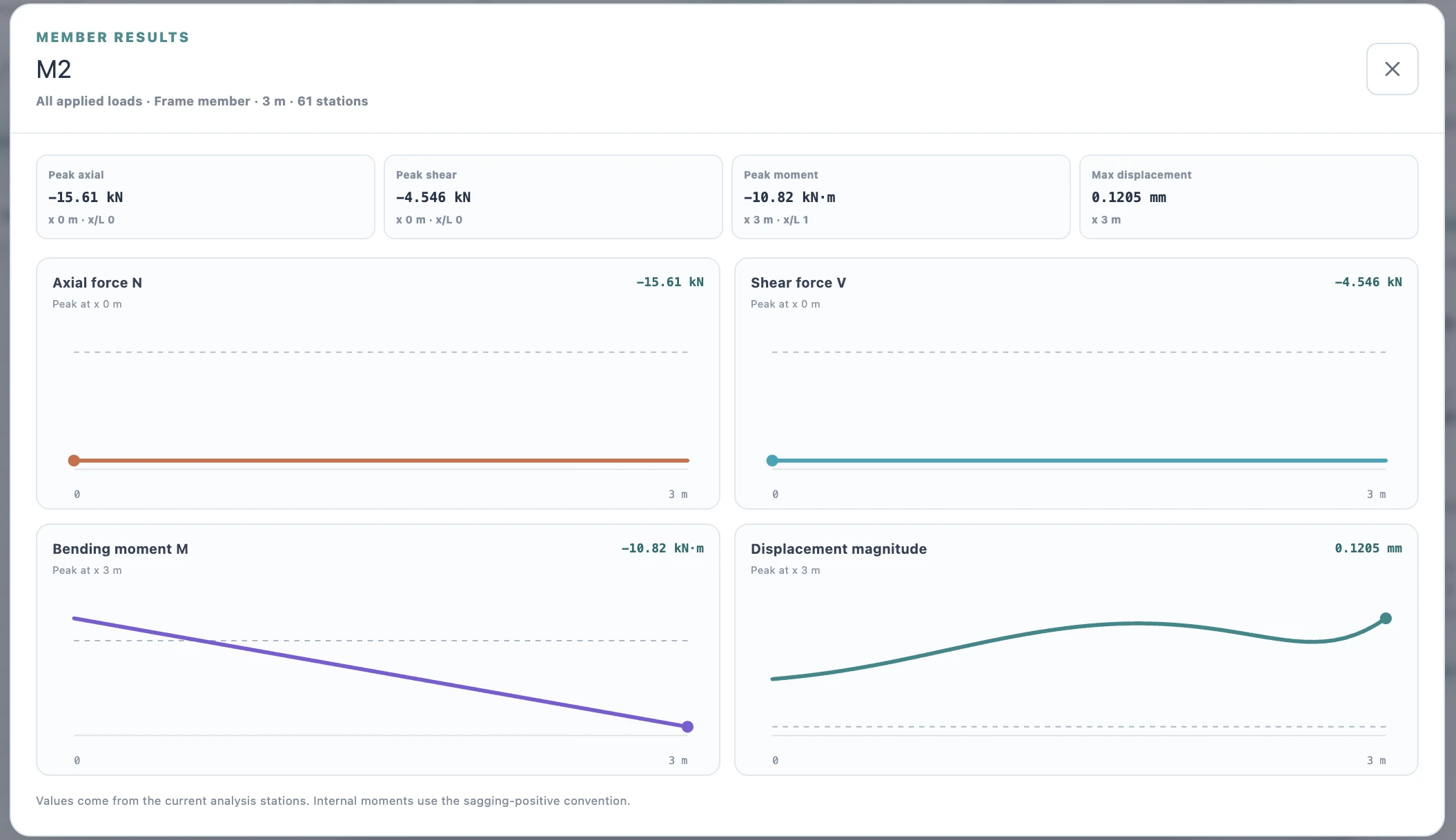
Optimal Beam Member M2 result window with axial, shear, moment and displacement values plus local response charts
Member M2 results · 61 calculated stations

Member-by-member inspection

Open a member and follow the response along its length

Review peak values, local end actions, station-by-station results, and response charts for the selected member. Axial force, shear force, bending moment, and displacement follow the same member orientation and sign convention used throughout the analysis and PDF report.

Axial force
−15.61 kN
Shear force
−4.546 kN
Bending moment
−10.82 kN·m
Maximum displacement
0.1205 mm

Example results shown for Member M2 under the selected load scenario.

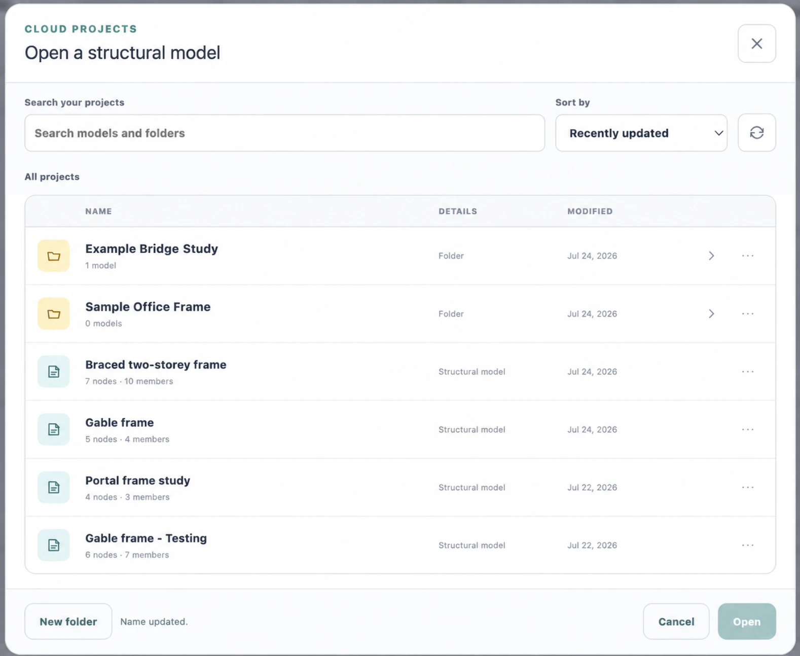
Optimal Beam Cloud Projects dialog with fictional example folders, saved structural models, search and recently updated sorting

Cloud Projects

Save, organize, and reopen every model

Save named beam and 2D models, organize related studies in folders, and search or reopen your work from any browser session. Use Save As to preserve the current model while creating a separate design alternative.

  • Beam and 2D models
  • Project folders
  • Saved design alternatives
View plans with cloud projects

PDF calculation report

The solved model becomes a reviewable calculation record

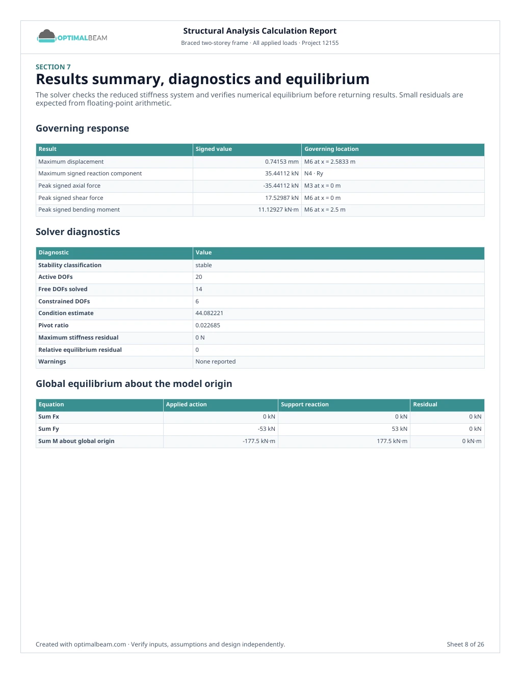
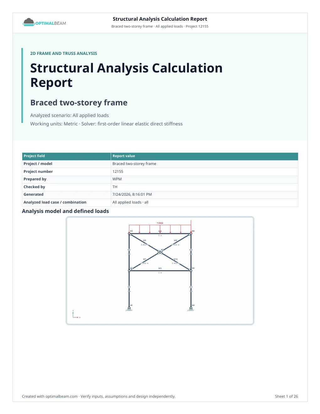
The example shown is the exported report for the braced two-storey frame used above. Across 26 sheets, it documents the structural model, analyzed scenario, solver checks, global response, and individual member results.

  • Analysis basis, scope, units, axes and sign conventions
  • Nodes, restraints, materials, sections, connectivity and releases
  • Loads, scenario factors, cases, combinations and self-weight
  • Solver checks, equilibrium, reactions and nodal displacements
  • Global diagrams and member sheets with station-based results
7nodes
10members
Passedequilibrium check
26report sheets

Add project and designer details to the calculation record. Professional reports can replace Optimal Beam branding with your company logo.

Figures describe the attached braced-frame report example. Report length and model size vary by project.

Explore reports and plans
Optimal Beam report sheet showing governing response, solver checks and global equilibrium
Results summary, solver checks and equilibrium
Cover sheet of an Optimal Beam Structural Analysis Calculation Report for a braced two-storey frame
Braced two-storey frame · report cover

From model to calculation report

Build the model. Analyze the response. Document the calculation.

Start with a focused beam study or open the full 2D workspace for frames and trusses. Analyze the response, inspect the results, and produce a documented calculation report.