01 / The problem
A steel floor beam with a clear design basis.
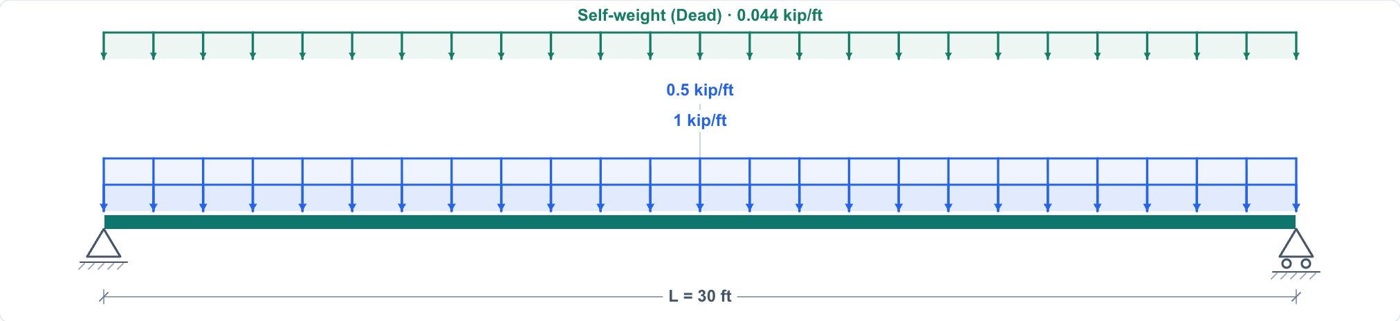
Check a uniform W21×44 ASTM A992 beam spanning 30 ft between an ideal pin and roller. It carries a full-span superimposed dead load of 0.5 kip/ft and live load of 1 kip/ft. Include the beam’s own weight, assume continuous compression-flange bracing, and use AISC 360-22 LRFD for strength.
This is a steel beam design example for a defined gravity-load case. A passing member check is one part of a complete structural design.
W21×44 properties used in this calculation
- dOverall depth
- 20.70 in
- bfFlange width
- 6.50 in
- twWeb thickness
- 0.350 in
- tfFlange thickness
- 0.450 in
- kdesDesign fillet distance
- 0.95 in
- ACross-sectional area
- 13.0 in²
- IxMajor-axis inertia
- 843 in⁴
- SxElastic section modulus
- 81.6 in³
- ZxPlastic section modulus
- 95.4 in³
- ryMinor-axis radius
- 1.26 in
- EElastic modulus
- 29,000 ksi
- FyYield strength
- 50 ksi
Explore the section properties ↗
02 / Calculation
Build the loads and combinations
Keep member self-weight in the dead load case. The entered 0.500 kip/ft dead load excludes the beam itself, so add the W21X44 weight once.
These are the selected gravity-only combinations for this teaching example. Establish the applicable building code and load standard, and include every required load, combination and pattern for an actual project. AISC 360 is the member-strength specification; it does not make this a complete project load assessment.
| Scenario | w (kip/ft) | Each reaction (kip) | Max. moment (kip-ft) |
|---|---|---|---|
| 1.4D | 0.7616 | 11.424 | 85.68 |
| 1.2D + 1.6L | 2.2528 | 33.792 | 253.44 |
| D + L | 1.544 | 23.16 | 173.7 |
| Live only | 1 | 15 | 112.5 |
03 / Calculation
Calculate reactions, shear and moment
The full-span UDL and symmetric pin-roller supports give equal reactions. Use the governing factored load for LRFD strength; use unfactored service loads for deflection.
Sagging moment is positive. The shear changes sign at midspan, where moment reaches its maximum. The ideal supports carry no end moment. The reaction is a demand on the support connection, not a completed connection or bearing check.
04 / Calculation
Check steel beam bending strength
First establish that the flange and web are compact. This rolled, doubly symmetric W shape is checked about its major axis, with continuous restraint of the compression flange and the required torsional restraint assumed.
AISC Table B4.1b (Cases 10 and 15), Sections F1 and F2, Eq. F2-1. Compactness permits plastic strength. Continuous bracing removes a finite unbraced segment from this example; LTB does not govern. For context, Lp = 1.76 ry sqrt(E/Fy) = 53.41 in. If restraint changes, evaluate the actual unbraced lengths and the applicable F2 lateral-torsional buckling provisions. Do not use the 30 ft span as proof of adequate bracing.
05 / Calculation
Check web shear strength
For this rolled W shape, the web slenderness falls just below the G2.1(a) limit. Use the applicable rolled-section shear factors, rather than automatically using the bending resistance factor.
AISC G2.1(a), Eqs. G2-1 and G2-2. The shear area is the overall depth d times web thickness tw; the clear height h is used for slenderness. The rolled-section factor criterion is checked with unrounded values. Bearing and web crippling at the supports remain separate checks.
06 / Calculation
Check total and live-load deflection
Use consistent inch-kip units in the elastic beam equation. These project limits are L/240 for total service load and L/360 for live load; they are chosen criteria for this example, not universal AISC limits.
Both maximum deflections occur at midspan. This is linear-elastic, small-displacement Euler-Bernoulli bending without shear deformation, composite stiffness or camber subtraction. Floor vibration and finishes-sensitive serviceability criteria are outside this example.
Total service deflection uses 76.7% of the allowed movement. This is more critical than the 70.8% bending utilization for this model.
07 / Alternative design method
What changes with ASD?
The same nominal section strengths can also be checked using ASD. Use the selected D + L strength combination here, not the LRFD-factored load.
AISC F1 and G2.1(a). The total and live deflection checks stay the same. LRFD and ASD are separate design methods; do not mix factored demands with ASD available strengths. The downloadable model includes the D + L ASD assignment.
08 / Steel beam sizing
Lighter or shallower? Compare the tradeoff.
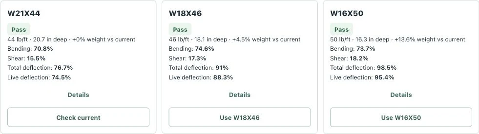
W21×44 is the lightest of these three passing alternatives. W18×46 and W16×50 reduce depth, but weigh more and use more of the deflection allowance. Recalculate self-weight for every candidate: the total dead loads become 0.544, 0.546 and 0.550 kip/ft respectively.
| Section | Weight (lb/ft) | Depth (in) | Bending | Shear | Total δ | Live δ |
|---|---|---|---|---|---|---|
| W21X44 | 44 | 20.7 | 70.8% | 15.5% | 76.7% | 74.5% |
| W18X46 | 46 | 18.1 | 74.6% | 17.3% | 91.0% | 88.3% |
| W16X50 | 50 | 16.3 | 73.7% | 18.2% | 98.5% | 95.4% |
Percentages are demand / available strength or project deflection limit. All values are calculated with each candidate’s own properties and self-weight. This comparison is not a universal span table or a claim that every project should use the lightest section.
09 / Reproduce the result
Open the inputs. Follow the calculation.
The loadable model includes the span, supports, W21×44 catalog section, named dead/live cases, combinations, automatic self-weight and example design assumptions. It opens in a new tab so you can keep this guide beside the calculator.
- Review Beam Input. Confirm 30 ft, the two distributed loads and automatic self-weight in the Dead case. The initial analysis view is service D + L.
- Run the analysis. For service D + L, expect 23.16 kip reactions and 173.70 kip-ft peak moment. Select LRFD 1.2D + 1.6L to see 33.792 kip and 253.44 kip-ft.
- Open Design and check the current section. Review A992, LRFD, continuous bracing, L/240 total and L/360 live. Compare the four utilization values with the summary above.
- Compare ASD. Change Method to ASD and check the current section again. Compare bending and shear with the ASD calculations above. The service deflection checks use the same limits.
- Try a depth constraint. Use Find sections, limit maximum depth, compare candidates and apply one. Then review the recalculated loads and checks.
The example PDF is free to download. Exporting your own live calculation reports follows your account plan. Changes to loads, span, section or restraint require a fresh check.
10 / Scope & references
Understand what this example establishes.
W21×44 passes the selected bending, shear, total deflection and live deflection checks for this model. The example does not establish connection design, support bearing or web crippling, bracing adequacy, vibration, fatigue, fire resistance, axial interaction, torsion, composite action or construction-stage stability.
Loads, combinations and serviceability criteria must match the actual project. This educational calculation is not a construction design or an independent engineering approval.
Review the product’s AISC verification evidence and scope ↗
- AISC 360-22 Specification for Structural Steel Buildings ↗
Table B4.1b, F1, F2, G2 and Appendix 6 for restraint design. Consult applicable errata.
- W21X44 catalog dimensions and properties ↗
AISC Shapes Database v16.0. US customary properties are used throughout; displayed metric values are not mixed into the calculations.
- University of Illinois Shi Lab: direct F2 worked check ↗
Independent reproduction of AISC Companion F.1-1B; methodological reference for compact, continuously braced W-shape flexure. It uses a different beam.
- University of Illinois Shi Lab: direct G2 worked check ↗
Independent reproduction of AISC Companion G.1B; methodological reference for rolled-section shear factors. It uses a different beam.
- Simply supported beam formulas ↗
Full-span UDL equilibrium and elastic deflection equations.