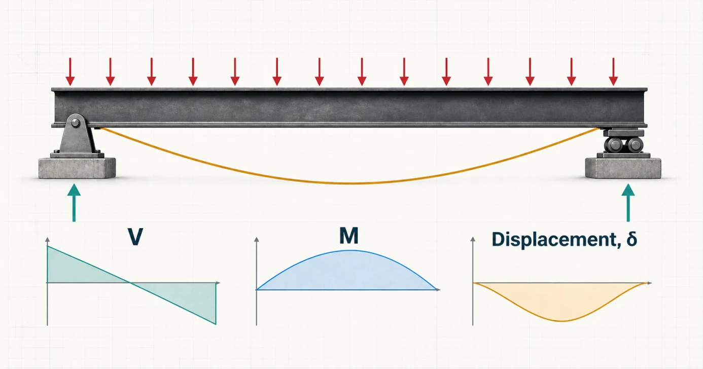
Quick answer
What is a simply supported beam?
A simply supported beam is restrained vertically at two locations while remaining free to rotate at those supports. The usual idealization is a pin at A and a roller at B: both provide a vertical reaction, the pin can also provide horizontal reaction, and the roller permits axial expansion or contraction.
The boundary conditions explain the response
Pin at A
Restrains horizontal and vertical translation but allows rotation.
Roller at B
Restrains vertical translation while allowing rotation and horizontal movement.
End moments
Are zero in this ideal model when there is no overhang or applied end couple.
Common approximations include floor joists bearing on walls, bridge girders on bearings, lintels over openings, and steel beams with simple shear connections. Real connections have some stiffness; the model is appropriate when that stiffness does not materially change the response you need.
From structure to model
Where simply supported beams appear in real life
The physical supports rarely look like textbook symbols. What matters is that they provide vertical reactions while allowing the beam ends to rotate, with one end free to accommodate longitudinal movement.
Bridges
Bridge girder on bearings
Idealized model
Pin-like bearing at one end; expansion bearing at the other.
- Why it fits
- Bearings carry vertical reaction while allowing end rotation, and one bearing can permit thermal movement along the span.
- Model with care
- Deck continuity, diaphragms, skew, multiple girders, bearing restraint and vehicle dynamics can make the real bridge a larger system.
Floors and roofs
Joist bearing on two walls
Idealized model
Simple bearing at each end with no intentional moment joint.
- Why it fits
- The joist delivers gravity load through end bearing and can rotate slightly as it bends between the supporting walls.
- Model with care
- Hangers, blocking, diaphragm action, built-in ends or continuity over a wall can introduce restraint and redistribute moment.
Openings in walls
Lintel over a window
Idealized model
Beam spanning between two bearing lengths.
- Why it fits
- The lintel collects wall and floor load above the opening and transfers it to masonry or concrete on each side.
- Model with care
- Masonry arching, composite action, connection details and insufficient bearing length can make a simple one-dimensional beam model incomplete.
Recognition rule: “simply supported” describes rotational behavior, not a specific material or connection. A bolted or welded beam can still be modeled as simple when its end moment is negligible for the result being checked.
Beam reaction calculator logic
How to calculate simply supported beam reactions
For vertical loading, solve equilibrium first: the upward reactions must equal the total downward load, and the sum of moments about either support must be zero.
Vertical equilibrium
ΣFy = 0
RA + RB equals the total applied vertical load.
Moments about A
ΣMA = 0
This equation usually gives RB directly.
Check
ΣMB = 0
An independent moment check catches distance and sign errors.
Point load at any position
For a point load P located a from the left support and b from the right support, where L = a + b:
Moving the load toward A increases RA and reduces RB. At midspan, a = b = L/2, so the reactions are equal at P/2. The quick calculator demonstrates that symmetric case; use the full solver to move the load to its real position.
Simply supported beam formulas
Reaction, moment, slope and deflection formulas
These formulas assume a straight prismatic beam with constant EI under static, small-deflection bending. Keep all force and length units consistent.
| Load case | Schematic | Support reactions | Maximum moment | Maximum deflection | End slope magnitude |
|---|---|---|---|---|---|
| Central point load P |
|
RA = RB = P/2 | Mmax = PL/4 | δmax = PL3/48EI | θ = PL2/16EI |
| Full-span UDL w |
|
RA = RB = wL/2 | Mmax = wL2/8 | δmax = 5wL4/384EI | θ = wL3/24EI |
| Point load P at a, b |
|
RA = Pb/L; RB = Pa/L | M under P = Pab/L | δ at P = Pa2b2/3EIL | Depends on a and b |
Need to compare this case with cantilever, fixed, overhanging or continuous supports? Browse the complete beam deflection formula library.
SFD and BMD
Shear force and bending moment diagrams
How to read the plots: positive shear and sagging moment are above their baselines; negative values are below. The dashed orange line is the exaggerated deflected shape.
Point load at midspan
Stepped shear, triangular moment
- Shear: +P/2 to the load, then a downward jump P to −P/2.
- Moment: linear from zero at each support to PL/4 at midspan.
- Deflection: symmetric with maximum PL3/(48EI) at midspan.
Full-span UDL
Linear shear, parabolic moment
- Shear: decreases linearly from +wL/2 to −wL/2.
- Moment: a parabola with maximum wL2/8 where shear is zero.
- Deflection: symmetric with maximum 5wL4/(384EI) at midspan.
A fast diagram check
Distributed load is the slope of the shear diagram, and shear is the slope of the moment diagram. A point load creates a jump in shear; a point moment creates a jump in moment. Maximum or minimum moment occurs where shear crosses zero, provided the location lies within the beam segment being checked.
Worked examples
Two complete simply supported beam hand checks
Compare a full-span UDL with a concentrated load at midspan. Each 6.0 m example follows the load through reactions, shear, maximum moment and deflection, with a matching model that opens in the full calculator.
6 m span · 10 kN/m UDL over the full span
- Span
- L = 6.0 m
- Uniform load
- w = 10 kN/m
- Flexural stiffness
- E = 200 GPa, I = 100 × 106 mm4
EI = 20,000 kN·m2
1 · Replace the UDL with its resultant
W = wL = 10 × 660 kN2 · Use symmetry and vertical equilibrium
RA = RB = W / 2 = 60 / 230 kN each3 · Maximum moment where shear is zero
Mmax = wL2 / 8 = 10(62) / 845 kN·m4 · Maximum midspan deflection
δmax = 5wL4 / 384EI = 5(10)(64) / [384(20,000)]8.44 mmSymmetry splits the 60 kN resultant equally. The shear diagram crosses zero at midspan, which is where the positive moment and downward deflection both peak. The 8.44 mm result is about L/711; assess it against the project’s actual criteria.
6 m span · 30 kN point load at midspan
- Span
- L = 6.0 m
- Point load
- P = 30 kN
- Flexural stiffness
- E = 200 GPa, I = 100 × 106 mm4
EI = 20,000 kN·m2
1 · Apply vertical equilibrium
RA + RB = PRA + RB = 30 kN2 · Use symmetry
RA = RB = P/2 = 30/215 kN each3 · Maximum moment at midspan
Mmax = PL/4 = 30(6)/445 kN·m4 · Maximum midspan deflection
δmax = PL3 / 48EI = 30(63) / [48(20,000)]6.75 mmThe point load creates a vertical jump in shear at midspan and a triangular positive moment diagram. The 6.75 mm midspan displacement is about L/889; compare it with the project’s governing limit.
Practical modeling
When the pin–roller model is appropriate
A “simple support” is a behavioral idealization, not a particular piece of hardware. A bearing seat, joist hanger, shear tab or bridge bearing may be modeled as simple when it transfers shear while allowing enough end rotation that support moment is negligible for the analysis objective.
Good candidates
- Floor or roof beams seated at two ends.
- Lintels with adequate bearing and no intentional end fixity.
- Bridge girders on pin/roller or elastomeric bearings.
- Steel members with connections detailed primarily for shear.
Use a different model when
- The member is monolithic with stiff columns or walls.
- The beam continues across more than two supports.
- An end extends past a support as an overhang.
- Axial restraint, uplift, settlement or connection slip matters.
Five frequent calculation mistakes
- Using P/2 for an eccentric load. Equal reactions only follow from symmetric loading.
- Treating w as the total force. A full UDL has resultant wL at its centroid.
- Measuring L to the beam ends instead of the reaction points. Use the support-to-support span for simple-beam formulas.
- Assuming maximum moment is always at midspan. It occurs where shear is zero; asymmetric loading moves that location.
- Mixing stiffness units. Convert E, I, loads and span into one compatible unit system before computing deflection.
Engineering basis
Assumptions and limits
- Beam theory: Euler–Bernoulli bending.
- Supports: ideal pin and roller at beam ends.
- Geometry: straight, slender, prismatic member.
- Material: homogeneous, linear elastic E.
- Response: static loads and small deflection.
- Not included: code design, buckling, vibration, connection or bearing checks.
Formula consistency and the checking process are documented in the sources and verification section below. Results are educational analysis outputs, not a substitute for project-specific design and review by a qualified engineer.
Sources and verification
Reference basis and checking process
The equations are classical, closed-form Euler–Bernoulli beam solutions. Coefficients and boundary-condition behavior for the simply supported central and eccentric point-load and full-span UDL cases were checked against the references below before the worked values were published.
Closed-form references
- American Wood Council, Beam Design Formulas with Shear and Moment Diagrams (DA 6) Reference configurations, reactions, shear, bending moment and elastic-deflection coefficients.
- University of Illinois Mechanics Reference, Beam Deflection Moment–curvature integration, Euler–Bernoulli assumptions and displacement boundary conditions.
How the examples were checked
Each expected value was recalculated from the displayed equation and checked against force and moment equilibrium where applicable. The worked-example links carry the same geometry, stiffness and loading into the calculator so the response diagrams can be compared with the hand check.
Review the published solver verification methodologyThese checks verify the stated idealized analysis cases; they do not constitute design certification or replace project-specific review of loading, restraints, stability, connections and governing requirements.
Frequently asked questions
Simply supported beam questions
What is a simply supported beam?
A simply supported beam is idealized with supports that prevent vertical movement but allow end rotation. The standard stable model uses a pin at one end and a roller at the other, so thermal expansion is not restrained in both horizontal directions.
What is the maximum deflection formula for a simply supported beam with a UDL?
For a prismatic, linear-elastic simply supported beam under a full-span uniformly distributed load, the maximum midspan deflection is delta = 5wL^4/(384EI).
What is the deflection formula for a simply supported beam with a center point load?
For a point load P at midspan, the maximum deflection occurs at midspan and is delta = PL^3/(48EI). Each support reaction is P/2 and the maximum bending moment is PL/4.
How do I calculate reactions for a point load that is not at midspan?
If the point load P is a distance a from the left support and b from the right support, with L = a + b, then the left reaction is Pb/L and the right reaction is Pa/L.
Why is bending moment zero at the supports of a simply supported beam?
The ideal pin and roller supports do not restrain beam rotation or transfer an applied couple into the beam. With no overhang or applied end moment, internal bending moment therefore reaches zero at each beam end.
Where does maximum bending moment occur on a simply supported beam?
Maximum or minimum bending moment occurs where shear is zero or changes sign. For a symmetric central point load or full-span UDL, this location is midspan.
What is a real-life example of a simply supported beam?
Common approximations include a floor joist bearing on two walls, a lintel with simple bearings, a bridge girder on bearings, or a steel beam connected to columns with simple shear connections.
What is the difference between a simply supported beam and a fixed beam?
A simply supported beam is free to rotate at its ideal pin and roller supports and has zero end moment. A fixed beam restrains end rotation, develops support moments, is statically indeterminate, and usually deflects less for the same span, EI and load.
When should I use the full beam calculator?
Use the full calculator for eccentric or multiple point loads, partial distributed loads, applied moments, overhangs, non-end supports, custom sections, mixed units, or complete downloadable result diagrams.