Steel Beam Sizes & Section Properties

Search, filter and compare standard steel sections from US AISC, Canadian CISC, British, European and Australian libraries. View dimensions and section properties, download size charts, or analyze any section in the Optimal Beam Calculator.

Search Sections Compare Sections Open in Beam Calculator Export Excel or PDF Open 2D Structural Analysis

Steel Section Finder

Search or browse standard steel sections.

Showing US AISC · W-Shapes · Imperial

AISC Shapes Database v16.0 · 2,299 sections

Searches every available library and shape family. Leave the field empty to browse the filters below.

Showing the most relevant 75 sections.

AISC W-shape dimensions and section properties in imperial units
Designation Weight (lb/ft) Depth, d (in) Flange width, bf (in) Area (in²) Ix (in⁴) Sx (in³)
W44x408 408 44.8 16.1 120 38700 1730
W44x368 368 44.4 16 108 34700 1560
W44x335 335 44 15.9 98.5 31100 1410
W44x290 290 43.6 15.8 85.4 27000 1240
W40x655 655 43.6 16.9 193 56500 2590
W44x262 262 43.3 15.8 77.2 24100 1110
W36x853 853 43.1 18.2 251 70000 3250
W36x925 925 43.1 18.6 272 73000 3390
W40x593 593 43 16.7 174 50400 2340
W44x230 230 42.9 15.8 67.8 20800 971
W36x802 802 42.6 18 236 64800 3040
W40x503 503 42.1 16.4 148 41600 1980
W36x723 723 41.8 17.8 213 57300 2740
W40x392 392 41.6 12.4 116 29900 1440
W40x431 431 41.3 16.2 127 34800 1690
W36x652 652 41.1 17.6 192 50600 2460
W40x397 397 41 16.1 117 32000 1560
W40x327 327 40.8 12.1 95.9 24500 1200
W40x331 331 40.8 12.2 97.7 24700 1210
W40x362 362 40.6 16 106 28900 1420
W40x372 372 40.6 16.1 110 29600 1460
W40x294 294 40.4 12 86.2 21900 1080
W40x278 278 40.2 12 82.3 20500 1020
W40x324 324 40.2 15.9 95.3 25600 1280
W40x264 264 40 11.9 77.4 19400 971
W40x297 297 39.8 15.8 87.3 23200 1170
W36x529 529 39.8 17.2 156 39600 1990
W40x235 235 39.7 11.9 69.1 17400 875
W40x277 277 39.7 15.8 81.5 21900 1100
W40x211 211 39.4 11.8 62.1 15500 786
W40x249 249 39.4 15.8 73.5 19600 993
W36x487 487 39.3 17.1 143 36000 1830
W36x387 387 39.1 12.7 114 26500 1360
W40x183 183 39 11.8 53.3 13200 675
W40x215 215 39 15.8 63.5 16700 859
W36x441 441 38.9 17 130 32100 1650
W40x199 199 38.7 15.8 58.8 14900 770
W40x167 167 38.6 11.8 49.3 11600 600
W36x350 350 38.6 12.6 103 23600 1220
W36x395 395 38.4 16.8 116 28500 1490
W40x149 149 38.2 11.8 43.8 9800 513
W36x318 318 38.2 12.4 93.4 21200 1110
W36x361 361 38 16.7 106 25700 1350
W36x286 286 37.8 12.3 83.9 18900 1000
W36x330 330 37.7 16.6 96.9 23300 1240
W36x256 256 37.4 12.2 75.3 16800 895
W36x302 302 37.3 16.7 89 21100 1130
W36x232 232 37.1 12.1 68 15000 809
W36x282 282 37.1 16.6 82.9 19600 1050
W36x262 262 36.9 16.6 77.2 17900 972
W36x210 210 36.7 12.2 61.9 13200 719
W36x247 247 36.7 16.5 72.5 16700 913
W36x194 194 36.5 12.1 57 12100 664
W36x231 231 36.5 16.5 68.2 15600 854
W36x182 182 36.3 12.1 53.6 11300 623
W36x170 170 36.2 12 50 10500 581
W36x160 160 36 12 47 9760 542
W33x387 387 36 16.2 114 24300 1350
W36x150 150 35.9 12 44.3 9040 504
W36x135 135 35.6 12 39.9 7800 439
W33x354 354 35.6 16.1 104 22000 1240
W33x318 318 35.2 16 93.7 19500 1110
W33x291 291 34.8 15.9 85.6 17700 1020
W33x263 263 34.5 15.8 77.4 15900 919
W33x241 241 34.2 15.9 71.1 14200 831
W33x221 221 33.9 15.8 65.3 12900 759
W33x169 169 33.8 11.5 49.5 9290 549
W33x201 201 33.7 15.7 59.1 11600 686
W33x152 152 33.5 11.6 44.9 8160 487
W33x141 141 33.3 11.5 41.5 7450 448
W30x391 391 33.2 15.6 115 20700 1250
W33x130 130 33.1 11.5 38.3 6710 406
W33x118 118 32.9 11.5 34.7 5900 359
W30x357 357 32.8 15.5 105 18700 1140
W27x539 539 32.5 15.3 159 25600 1570
Previous Page 1 of 4 Next

Steel Beam Size Charts by Region and Standard

Browse all 6,691 integrated steel sections by country, regional standard and section family. Every family link opens its complete size chart with searchable dimensions, weights and section properties.

How to Use the Steel Section Finder

  1. Search or browse

    Enter a complete designation such as W12×26, W310×39 or IPE 300, or select a regional library, shape family and depth series.

  2. Filter by dimensions and properties

    Use advanced filters to narrow sections by maximum depth, maximum weight, minimum Ix and minimum Sx.

  3. Preview and compare

    Select a row to see its labelled cross-section. Check multiple sections to compare their dimensions and properties side by side.

  4. Open it in the Beam Calculator

    Choose “Analyze in Beam Calculator” to open a new beam model with the selected section properties already loaded for slope, deflection and stress analysis.

Understanding Steel Beam Designations

Steel section labels encode family, size and weight differently by region. Use the examples below to read common US, Canadian, British and European designations.

What does W12×26 mean?

W12×26 is an American wide-flange steel section. “W” identifies the shape family, “12” is the approximate nominal depth in inches, and “26” is the nominal weight in pounds per foot. The actual depth can differ from the nominal designation, so the tabulated dimensions should be used for analysis and detailing.

What does W310×39 mean?

In the Canadian metric designation W310×39, “310” represents the approximate nominal depth in millimetres and “39” represents the nominal mass in kilograms per metre.

What does UB 406×178×67 mean?

A British universal beam such as UB 406×178×67 is read as approximate depth × flange width × mass per metre: about 406 mm deep, 178 mm flange width, and 67 kg/m.

What does IPE 300 mean?

IPE 300 belongs to the European IPE family. “300” is the nominal section depth in millimetres. Actual depth, flange width and thickness vary by product and should be taken from the selected steel library.

Steel Beam Dimensions and Section Properties Explained

These symbols appear in the steel section finder and PDF charts. Use the table below to understand what each property represents and why it matters in beam and column design.

Symbol Property What it represents Common units Why it matters
d Overall depth Distance between the outer flange faces in, mm Influences stiffness, clearance and bending behaviour
bf Flange width Overall width of the flange in, mm Affects lateral stability and y-axis behaviour
tw Web thickness Thickness of the vertical web in, mm Important for shear resistance
tf Flange thickness Thickness of the flange in, mm Important for flexural resistance and local slenderness
A Cross-sectional area Total steel area in2, mm2 Used for weight, axial stress and average shear stress
Ix Moment of inertia about the x-axis Distribution of area about the x-axis in4, mm4 Controls flexural stiffness and deflection about the x-axis
Iy Moment of inertia about the y-axis Distribution of area about the y-axis in4, mm4 Controls stiffness about the y-axis
Sx Elastic section modulus Ix divided by the extreme-fibre distance in3, mm3 Used for elastic bending stress
Sy Elastic section modulus about the y-axis Elastic modulus about the y-axis in3, mm3 Used for bending stress about the y-axis
Zx Plastic section modulus Plastic bending property about the x-axis in3, mm3 Used in plastic flexural resistance calculations
Zy Plastic section modulus about the y-axis Plastic property about the y-axis in3, mm3 Used in plastic resistance about the y-axis
rx Radius of gyration about the x-axis √(Ix/A) in, mm Used in member slenderness calculations
ry Radius of gyration about the y-axis √(Iy/A) in, mm Often important for column and lateral stability
J Torsional constant Saint-Venant torsional property in4, mm4 Used in torsional and stability calculations
Cw Warping constant Resistance associated with nonuniform warping in6, mm6 Used in lateral-torsional buckling analysis

Types of Structural Steel Sections

Steel libraries use different designations for similar families. Use the crosswalk below to open the matching catalog for each region.

Pipe

Round sections designated according to nominal pipe sizing conventions.

How to Compare and Select a Steel Beam Size

A section with a larger moment of inertia is generally stiffer about the corresponding axis, but that does not automatically make it suitable for a particular beam. The required section depends on the span, support conditions, applied loads, material grade, unbraced length, deflection criteria and applicable design standard.

Practical selection workflow

  1. Establish span and support conditions.

  2. Define dead, live and other applicable loads.

  3. Select the appropriate material and regional standard.

  4. Identify candidate sections based on depth, weight and stiffness.

  5. Analyze reactions, shear, moment, slope and deflection.

  6. Complete the applicable strength, stability and serviceability checks.

  7. Compare passing alternatives for weight and constructability.

Analysis workflows

Use Steel Sections in Beam and 2D Structural Analysis

For a line beam, select a section and choose “Analyze in Beam Calculator” to open a model with its properties already loaded. For portal frames, trusses, braced frames and other connected systems, open the 2D Structural Analysis app and assign standard or custom sections to each member.

  • Simply supported, cantilever, fixed and continuous beams
  • Point loads, distributed loads and applied moments
  • Multiple sections along a beam
  • Slope and deflection diagrams
  • Bending and shear stress results
  • PDF calculation reports
  • Saved models
  • AI-assisted beam model generation
Calculation Report PDF
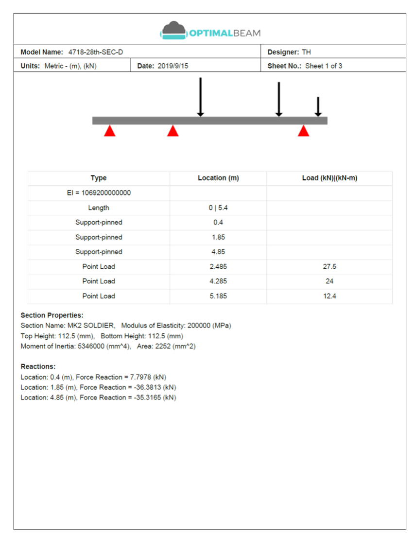
Beam calculation PDF report page showing the beam model, loads, supports, section properties, and reactions
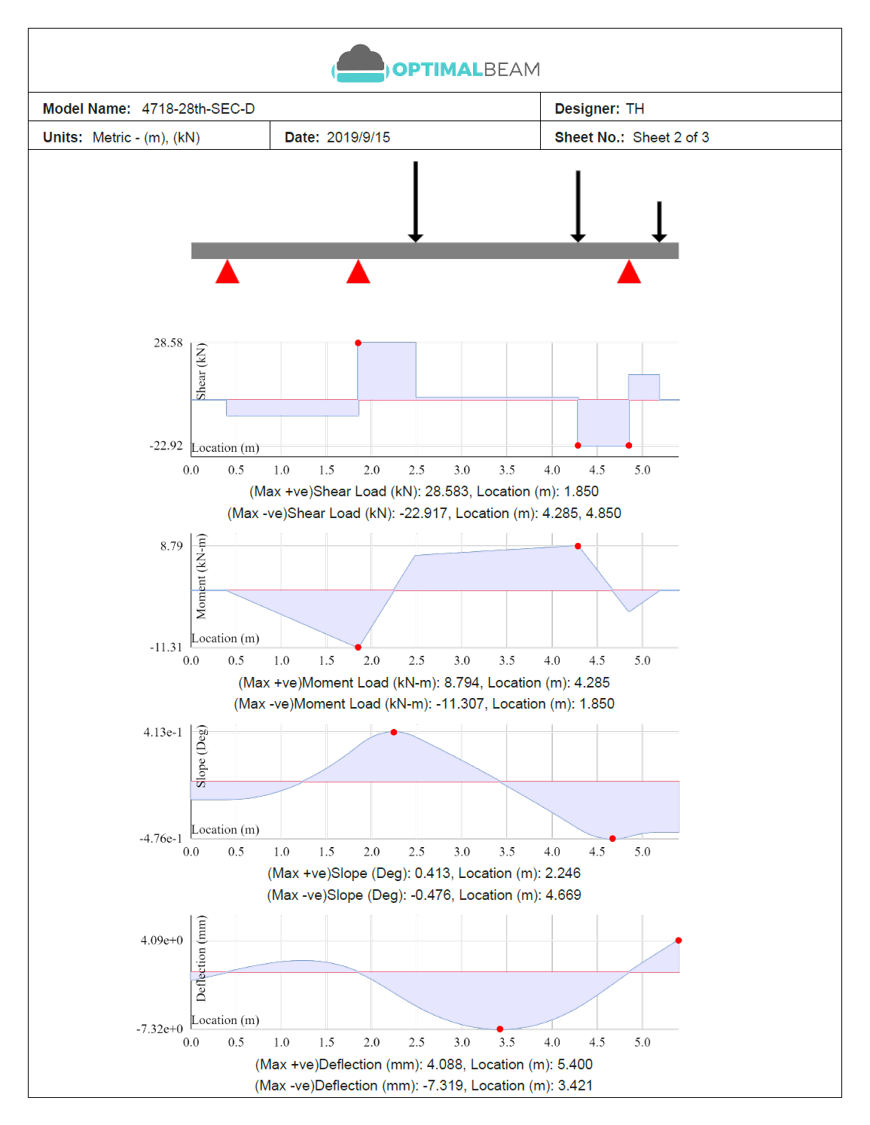
Beam calculation PDF report page showing shear, moment, slope, and deflection diagrams

PDF downloads

Download section sheets and size charts for calculation packages

Get printable Optimal Beam PDFs instantly from the finder—no email wait. Use a section sheet for one designation, or a size chart for the family or group you are browsing.

  • Section sheet with dimensional schematic
  • Geometry and section properties tables
  • Family or group size charts from the toolbar
  • Imperial or metric units from your current view
Get a section sheet

Select a section above, then use Download PDF on the selected card.

Optimal Beam PDF

W12x26

AISC · Wide flange · Imperial

Not to scale

Geometry

Prop Val Prop Val
Wt 26 d 12.2

Section properties

Prop Val Prop Val
Ix 204 Iy 29.1

Methodology

Data sources

Optimal Beam preserves the underlying published source values and uses normalized values for unit conversion and calculations. Values displayed in the table may be rounded for readability. Confirm critical dimensions and properties against the official publisher’s tables before fabrication or final design.

AISC Shapes Database v16.0

Active library
Source / publisher
AISC (American Institute of Steel Construction)
Edition / version
Shapes Database v16.0
Sections
2,299
Last verified
July 2026

CISC Structural Section Tables SST12.1

Source / publisher
CISC (Canadian Institute of Steel Construction)
Edition / version
Structural Section Tables v12.1
Sections
1,514
Last verified
July 2026

Eurocode 3 UK National Annex and ArcelorMittal Sections 2026-1

Source / publisher
CEN / European steel sections
Edition / version
European Steel Sections v2026.1
Sections
1,239
Last verified
July 2026

British-Sections-1 and Eurocode 3 UK shared angle/hollow tables

Source / publisher
UK / British steel sections
Edition / version
Steel Sections v2023.11
Sections
1,196
Last verified
July 2026

Australian-Sections.xlsx (Sheets 1-19)

Source / publisher
Australian steel sections
Edition / version
Australian Steel Sections v2019.11
Sections
443
Last verified
July 2026

Reviewed by Tamer Hijjawi, P.Eng.

Last verified: July 2026

Report a suspected data issue

Questions & answers

Frequently Asked Questions

What do the numbers in a steel beam designation mean?

The numbers encode size differently by library. In AISC W12×26, 12 is the approximate nominal depth in inches and 26 is the weight in pounds per foot. In Canadian W310×39, 310 is the approximate depth in millimetres and 39 is the mass in kilograms per metre. British UB designations use depth × flange width × mass, while IPE 300 uses a nominal depth in millimetres. Always use the tabulated dimensions for detailing and analysis.

What is the difference between an I-beam and a W-beam?

“I-beam” is an informal name for I-shaped sections. A W-beam is an AISC wide-flange shape—the common rolled I-section with parallel flanges. American standard S shapes are also I-shaped but use different flange geometry. Other libraries use designations such as UB, UC or IPE for similar families.

What is the difference between nominal depth and actual depth?

Nominal depth is the rounded depth used in the designation, such as the “12” in W12×26. Actual depth is the published overall depth from the steel table and can differ from the nominal value. Use the tabulated depth for clearance, connections and analysis.

What is the difference between Ix, Sx and Zx?

Ix is the moment of inertia about the x-axis and governs stiffness and deflection. Sx is the elastic section modulus about the x-axis and is used in elastic bending stress checks. Zx is the plastic section modulus about the x-axis and is used for plastic bending strength of suitable ductile sections. None of these alone is a complete code design check.

How do I compare two steel beam sizes?

Select multiple sections with the compare checkboxes to review depth, weight, Ix, Sx and related properties side by side. For project suitability, send candidates to the Optimal Beam calculator and compare them under the same span, supports and loads.

Can I switch between imperial and metric units?

Yes. Use the Metric / Imperial toggle in the steel section finder. Display values are normalized for the selected unit system while the original source data remains stored in the database.

Which steel section libraries are included?

The finder includes 6,691 sections from AISC Shapes Database v16.0, Canadian CISC Structural Section Tables SST12.1, and the integrated European, British and Australian libraries across rolled, welded, angle, tee, channel, pipe and hollow-section families.

Can I download the steel beam size chart?

Yes. Use Export Excel or Export PDF in the finder toolbar. Both exports include the sections that match your current family, unit system and active filters. For a single designation, select the section and use Download PDF on the selected card.

Can I analyze a selected section in the beam calculator?

Yes. Choose Analyze on a selected section to open the Optimal Beam calculator with that section’s geometric and section properties loaded into a new beam model. Then define the span, supports and loads to calculate reactions, shear, moment, slope, deflection and stress.

Does a higher Ix mean a beam can carry more load?

No. A higher Ix means the section is generally stiffer about that axis, which often reduces deflection, but it does not by itself determine load capacity. Capacity depends on span, support conditions, loads, material grade, unbraced length, deflection limits and the applicable design standard.

Does this tool determine the correct beam size for my project?

No. This page helps you browse, compare and analyze steel sections. Selecting the correct beam for a project requires engineering judgment and the applicable strength, stability and serviceability checks for your design standard.

Are the section dimensions suitable for fabrication or final design?

Use these values as a convenient reference from published steel shape libraries. Before fabrication or final design, confirm critical dimensions and properties against the publisher’s official tables for the edition you are using.