Quick answer
What is a fixed beam?
A fixed beam has both ends restrained against translation and rotation. It is also called a fixed-fixed beam, built-in beam, clamped beam or encastré beam. Because end rotation is prevented, the supports develop bending moments as well as force reactions.
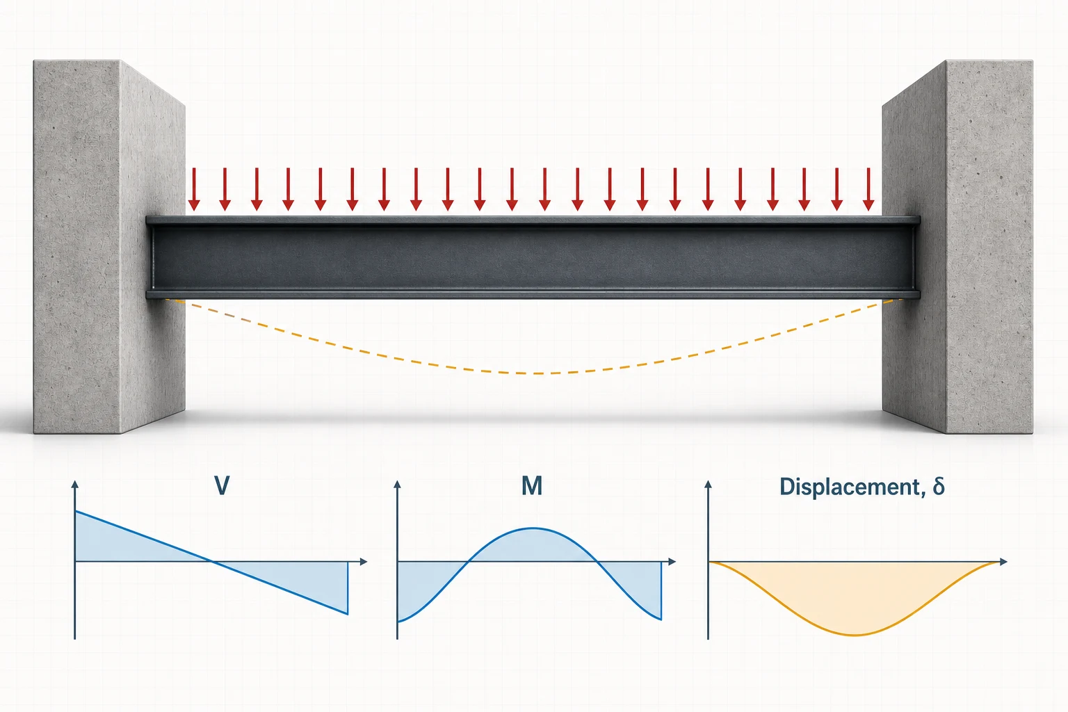
Under ordinary downward gravity loading, the beam usually has negative (hogging) moment near both ends, positive (sagging) moment in the span, and points of contraflexure where the moment changes sign.
Read the restraint before the formulas
Both ends fixed
The ideal supports prevent slope and vertical displacement at A and B.
End moments
Rotational restraint creates non-zero hogging moments at both supports.
Span response
The beam still bends between supports and normally develops positive moment near midspan.
From structure to model
Where fixed beams appear in real life
The fixed-fixed idealization is useful when both surrounding supports strongly restrain end rotation. Real joints have finite stiffness, so these examples are candidates for the model rather than proof of perfect fixity.
Concrete construction
Monolithic concrete frame beam
Idealized model
Rotation restrained at both beam–column joints.
- Why it fits
- A beam cast continuously with substantial columns can develop hogging moments at both joints and sagging moment in the span.
- Model with care
- Column and foundation flexibility redistribute moment. Analyze the full frame when joint rotation is important rather than assuming infinitely rigid ends.
Machines and test rigs
Clamped machine crossmember
Idealized model
Rigid clamp at each end of a short member.
- Why it fits
- Deep bolted or welded end blocks can suppress slope at both ends, creating the characteristic double-curvature response.
- Model with care
- Bolt slip, local plate flexibility, contact and vibration can dominate. The clamp stiffness should be checked against the member stiffness.
Steel buildings
Steel moment-frame girder
Idealized model
Moment-resisting connection at both beam–column joints.
- Why it fits
- Extended end plates, bolt groups and stiffened haunches can transfer end moment into the columns and strongly restrain beam-end rotation.
- Model with care
- Connection, panel-zone and column flexibility make the joints semi-rigid in practice. Use the verified connection stiffness when it materially affects the response.
Recognition rule: fixity is relative stiffness. A connection that looks rigid may still rotate enough to invalidate fixed-end coefficients, while a monolithic joint may be close to fixed for one check but not another.
Fixed beam formulas
Fixed-end moments, reactions and deflection
These closed-form cases assume a straight prismatic member, constant EI, level supports and perfect fixity at both ends. Positive moment is sagging; negative moment is hogging.
| Load case | Schematic | Reactions | Support moments | Positive span moment | Maximum deflection |
|---|---|---|---|---|---|
| Full-span UDL w |
|
RA = RB = wL/2 | MA = MB = −wL2/12 | Mmid = +wL2/24 | δmax = wL4/(384EI) |
| Point load P at midspan |
|
RA = RB = P/2 | MA = MB = −PL/8 | Mmid = +PL/8 | δmax = PL3/(192EI) |
Useful locations: for the UDL case, zero moment occurs at x = 0.2113L and 0.7887L. For a central point load, the inflection points are at L/4 and 3L/4. End slopes and end deflections are zero in both ideal cases.
Comparing support systems or looking for V(x), M(x), slope and elastic-curve equations? Use the complete beam deflection formula library.
Fixed beam SFD and BMD
How the load changes shear, moment and deflection
The support reactions can look deceptively similar to a simply supported beam, but the bending diagram is fundamentally different because both end rotations are restrained.
How to read the plots: positive shear and sagging moment are above their baselines; negative values are below. The dashed orange line is the exaggerated deflected shape.
Full-span UDL
UDL over full span
Constant load intensity w from fixed end A to fixed end B.
- Shear: linear from +wL/2 to −wL/2.
- Moment: −wL²/12 at each end and +wL²/24 at midspan.
- Deflection: symmetric, with wL⁴/(384EI) at midspan.
Point load at midspan
P at midspan
Concentrated load P at the center of a fixed-fixed span.
- Shear: +P/2 to the load, then −P/2.
- Moment: equal-magnitude −PL/8 end moments and +PL/8 at the load.
- Deflection: symmetric, with PL³/(192EI) at midspan.
Worked calculations
Two complete fixed beam examples
Each example keeps the same model used by the interactive calculator so the arithmetic, diagrams and full-solver handoff can be checked against one another.
6 m fixed beam with 10 kN/m UDL
Steel-like E = 200 GPa · I = 100 × 106 mm4
- Span
- L = 6 m
- Uniform load
- w = 10 kN/m
- Elastic modulus
- E = 200 GPa
- Second moment of area
- I = 100 × 106 mm4
- Flexural stiffness
- EI = 20,000 kN·m2
1 · Vertical reactions
RA = RB = wL/2 = 10(6)/230 kN each2 · Fixed-end moments
MA = MB = −wL2/12−30 kN·m3 · Positive midspan moment
Mmid = wL2/24+15 kN·m4 · Maximum deflection
δmax = wL4/(384EI)1.69 mmThe support moment magnitude is twice the positive midspan moment. A strength check therefore needs both hogging and sagging regions, and reinforcement or lateral restraint may differ between them.
6 m fixed beam with a 30 kN center load
Same EI as Example 1 for a direct response comparison
- Span
- L = 6 m
- Point load
- P = 30 kN
- Elastic modulus
- E = 200 GPa
- Second moment of area
- I = 100 × 106 mm4
- Flexural stiffness
- EI = 20,000 kN·m2
1 · Vertical reactions
RA = RB = P/2 = 30/215 kN each2 · Fixed-end moments
MA = MB = −PL/8−22.5 kN·m3 · Moment under the load
Mmid = +PL/8+22.5 kN·m4 · Maximum deflection
δmax = PL3/(192EI)1.69 mmFor this symmetric point load, the hogging support moments and sagging midspan moment have the same magnitude. The bending diagram crosses zero at L/4 and 3L/4.
Practical fixed-end modeling
When is the fixed-fixed model appropriate?
Fixed beams appear in monolithic concrete frames, rigid moment frames, deep wall-to-wall members and some laboratory or machine components. The essential requirement is rotational restraint at both ends—not the material or connection label by itself.
Need the moment of inertia for a nonstandard profile? Use the free custom and arbitrary cross-section properties calculator for built-up geometry, polygons and DXF imports.
Good candidates
- Monolithic beam–wall or beam–column joints with substantial rotational stiffness.
- Members clamped into massive supports on both ends.
- Symmetric textbook checks where support settlement is negligible.
- Constant-EI members in linear-elastic, small-deflection response.
Use a different model when
- Connections behave as pins or have meaningful semi-rigid rotation.
- Supports settle, rotate or have unequal stiffness.
- The member continues into adjacent spans.
- Cracking, yielding, large deflection, shear deformation or changing EI materially affects response.
Five frequent calculation mistakes
- Assuming every rigid-looking joint is perfectly fixed. Connection and framing stiffness control the actual moment restraint.
- Reporting only the positive span moment. The negative support moments can be larger and reverse the tension face.
- Using simply supported deflection formulas. Rotational restraint changes both curvature and the coefficient.
- Ignoring contraflexure. Moment changes sign, which matters for reinforcement, bracing and interpretation.
- Mixing length units in EI. Convert E, I, load and span to one compatible unit system before calculating deflection.
Boundary-condition comparison
Fixed beam vs. simply supported beam
| Question | Fixed-fixed beam | Simply supported beam |
|---|---|---|
| End rotation | Restrained at both ends | Allowed at pin and roller |
| Support moment | Normally non-zero | Zero in the ideal model |
| UDL maximum moment | |M| = wL²/12 at supports | M = wL²/8 at midspan |
| UDL maximum deflection | wL⁴/384EI | 5wL⁴/384EI |
| Analysis type | Statically indeterminate | Statically determinate |
For equal L, w and EI, the ideal fixed-fixed UDL deflection is one-fifth of the simply supported value. That advantage depends on the real end restraint being present and maintained.
Engineering basis
Assumptions and limits of the formulas
- Beam theory: Euler–Bernoulli bending.
- Geometry: straight, slender, prismatic member.
- Supports: zero vertical displacement and zero rotation at both ends.
- Material: homogeneous and linear elastic.
- Response: static load and small deflection.
- Not included: code design, connection stiffness, settlement, buckling or dynamics.
Closed-form coefficients were cross-checked against the American Wood Council Design Aid 6 fixed-at-both-ends cases and the live explorer equations. The guide is educational analysis, not project-specific design.
Sources and verification
Reference basis and checking process
The equations are classical, closed-form Euler–Bernoulli beam solutions. Coefficients and boundary-condition behavior for the fixed-fixed center-point-load and full-span UDL cases were checked against the references below before the worked values were published.
Closed-form references
- American Wood Council, Beam Design Formulas with Shear and Moment Diagrams (DA 6) Reference configurations, reactions, shear, bending moment and elastic-deflection coefficients.
- University of Illinois Mechanics Reference, Beam Deflection Moment–curvature integration, Euler–Bernoulli assumptions and displacement boundary conditions.
How the examples were checked
Each expected value was recalculated from the displayed equation and checked against force and moment equilibrium where applicable. The worked-example links carry the same geometry, stiffness and loading into the calculator so the response diagrams can be compared with the hand check.
Review the published solver verification methodologyThese checks verify the stated idealized analysis cases; they do not constitute design certification or replace project-specific review of loading, restraints, stability, connections and governing requirements.
Frequently asked questions
Fixed beam questions
What is a fixed beam?
A fixed beam, also called a fixed-fixed, built-in, clamped-clamped or encastré beam, has both ends restrained against translation and rotation in the ideal model.
What is the fixed beam deflection formula for a full-span UDL?
For a prismatic fixed-fixed beam with uniform load w across span L, the maximum deflection is wL^4/(384EI) at midspan.
What are the fixed-end moments for a UDL?
The support moments are equal hogging moments, MA = MB = -wL^2/12, while the positive midspan moment is +wL^2/24.
What are the fixed-end moments for a center point load?
A central point load P gives MA = MB = -PL/8 and a positive midspan moment of +PL/8. Each vertical reaction is P/2.
Where are the points of contraflexure in a fixed beam under UDL?
For a full-span UDL, zero moment occurs at approximately 0.2113L and 0.7887L from the left end.
Is a real beam connection perfectly fixed?
Rarely. A connection may be treated as fixed only when its rotational stiffness and the surrounding frame justify that idealization for the analysis objective.
Is a fixed beam statically determinate?
No. A fixed-fixed beam is statically indeterminate, so equilibrium alone cannot determine all reactions; deformation compatibility and stiffness are also required.
When should I use the full beam calculator?
Use it for partial or multiple loads, off-center point loads, applied moments, varying EI, settlements, semi-rigid behavior or when you need full diagrams and report-ready results.