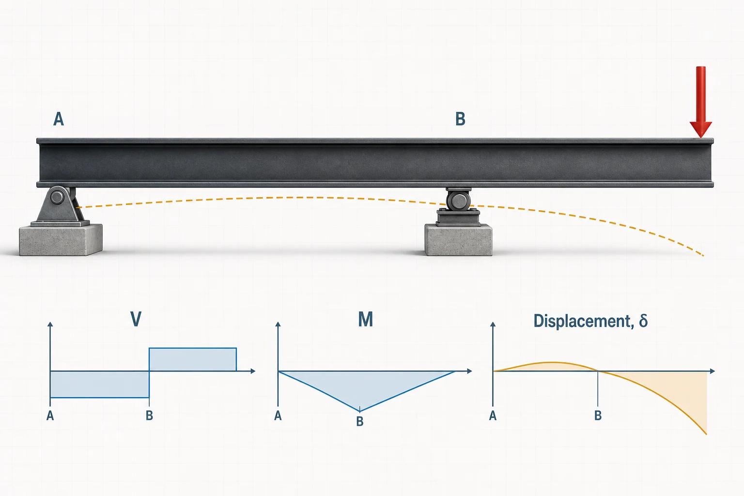
Quick answer
What is an overhanging beam?
An overhanging beam extends past at least one of its supports. This guide uses a pin at A, a roller at B, a support-to-support span L, and a right overhang a from B to the free tip. The total member length is therefore L+a.
The supported span and overhang act together. Loads beyond B create negative moment over the roller and can produce a negative reaction (uplift) at A; loads over the full length can create both positive span moment and negative overhang moment.
Read the three regions correctly
Pin A
Provides vertical and horizontal restraint but no ideal support moment.
Roller B
Provides the second vertical reaction and sits inside the total beam length.
Free tip
Carries no support reaction; the overhang length a strongly affects uplift and deflection.
From structure to model
Where overhanging beams appear in real life
An overhanging beam has two or more supports with the member continuing past an outer support. The supported span provides a backspan that balances load on the projection.
Roofs
Roof beam extending to an eave
Idealized model
Supported between walls; continued past the exterior wall.
- Why it fits
- The inboard roof span and projecting eave are one member, so snow or cladding load beyond the wall creates negative moment at that support.
- Model with care
- Rafter action, roof diaphragm behavior, uplift connectors and a fascia or exterior post can change the idealized beam and its load path.
Platforms and balconies
Platform beam past an outer column
Idealized model
Pin and inboard column support with a free projecting tip.
- Why it fits
- The backspan between columns stabilizes a usable platform area that extends beyond the exterior support.
- Model with care
- Check uplift at the remote support, torsion from edge loading, vibration and whether the floor system distributes load to neighboring beams.
Stations and loading areas
Canopy beam beyond the last column
Idealized model
Two supports with the beam continuing to a free canopy edge.
- Why it fits
- Passing the beam over the outer column keeps the edge column-free while the interior bay acts as a balancing backspan.
- Model with care
- Wind uplift, ponding, moment connections and any brace or hanger at the tip can reverse loads or change the support model.
Recognition rule: the outer support sits inside the total beam length. If the projection begins at a fully fixed wall and there is no second support, it is a cantilever instead.
Overhanging beam formulas
Reactions, support moment and deflection formulas
These equations use span L between supports, right overhang a, total length L+a, downward load magnitudes, positive sagging moment and downward deflection as positive. They apply to the exact single-overhang geometry shown.
| Load case | Schematic | Reaction at A | Reaction at B | Critical bending | Deflection references |
|---|---|---|---|---|---|
| Point load P at free tip |
|
RA = −Pa/L | RB = P(L+a)/L | MB = −Pa | Free tip: δtip = Pa2(L+a)/(3EI)Center of supported span A–B: δAB,center = −PaL2/(16EI) at x = L/2 from AMaximum within supported span A–B: δAB,max = −PaL2/(9√3 EI) at x = L/√3 from A |
| UDL w over total L+a |
|
RA = w(L2−a2)/(2L) | RB = w(L+a)2/(2L) | MB = −wa2/2 | Free tip: δtip = wa(−L3+4La2+3a3)/(24EI)Center of supported span A–B: δAB,center = wL2(5L2−12a2)/(384EI) at x = L/2 from A |
Deflection sign and location: positive values are downward and negative values are upward. The center-of-A–B value is a reference at the halfway point between the two supports; it is not necessarily the largest deflection within A–B or along the complete beam. For the full-length UDL, δAB,center changes sign when a/L = √(5/12) ≈ 0.646. The calculator evaluates the complete deflected shape. Bending check: when RA is positive, the full-length UDL has zero shear at x = RA/w and positive moment RA2/(2w); compare it with |MB| = wa2/2.
Comparing support systems or looking for V(x), M(x), slope and elastic-curve equations? Use the complete beam deflection formula library.
Overhanging beam SFD and BMD
Why span loads and overhang loads change the signs
The roller creates a shear jump, the overhang creates negative bending near B, and the deflected shape can cross the support line. Reading only one “maximum” number misses that behavior.
How to read the plots: positive shear and sagging moment are above their baselines; negative values are below. The dashed orange line is the exaggerated deflected shape.
Full-length UDL
w over L+a
Uniform load from pin A through the overhang free tip.
- Reactions: depend on both L and a; their sum is w(L+a).
- Moment: positive in part of AB and negative near B.
- Deflection: can peak inside span A–B and reverse direction on the overhang.
Point load at the free tip
P at x = L+a
Concentrated load at the end of the projecting overhang.
- Reaction A: −Pa/L, so a hold-down may be required.
- Moment: linear, with −Pa at support B.
- Deflection: the span lifts while the free tip moves downward.
Worked calculations
Two complete overhanging beam examples
The same span and overhang are used in both examples so the effect of load extent is easy to compare.
6 m span + 2 m overhang with a 10 kN tip load
Pin A at x = 0 · roller B at x = 6 m · free tip at x = 8 m
- Span
- L = 6 m
- Overhang
- a = 2 m
- Point load
- P = 10 kN
- Elastic modulus
- E = 200 GPa
- Second moment of area
- I = 100 × 106 mm4
1 · Moment equilibrium about A
RBL = P(L+a)RB = 13.33 kN2 · Vertical equilibrium
RA + RB − P = 0RA = −3.33 kN3 · Moment at support B
MB = −Pa = −10(2)−20.0 kN·m4 · Free-tip deflection
δtip = Pa2(L+a)/(3EI)5.33 mm down5 · Center of supported span A–B
δAB,center = −PaL2/(16EI) at x = L/2 from A2.25 mm up at x = 3.00 m6 · Maximum deflection within supported span A–B
δAB,max = −PaL2/(9√3 EI) at x = L/√3 from A2.31 mm up at x = 3.46 mThe load is only 10 kN, but lever action makes R_B exceed the load and forces R_A negative. The support at A needs 3.33 kN of hold-down capacity before load factors and combinations are considered.
6 m span + 2 m overhang with 10 kN/m UDL
Uniform load acts over the complete 8 m member
- Span
- L = 6 m
- Overhang
- a = 2 m
- Uniform load
- w = 10 kN/m
- Input
- total load W = 80 kN
- Flexural stiffness
- EI = 20,000 kN·m2
1 · Support reactions
RA = w(L²−a²)/(2L); RB = W−RA26.67 kN; 53.33 kN2 · Negative moment at B
MB = −wa²/2 = −10(2²)/2−20.0 kN·m3 · Positive span maximum
x = RA/w = 2.667 m; M = RA²/(2w)+35.56 kN·m4 · Center of supported span A–B
δAB,center = wL²(5L²−12a²)/(384EI) at x = L/2 from A6.19 mm down at x = 3.00 m5 · Largest deflection anywhere from A to the free tip
Compare the local peak in A–B with the free tip; use the larger |δ|6.21 mm downx ≈ 2.86 m from A, inside A–B
The positive span moment governs this geometry even though the beam has a visible overhang. The largest movement occurs at the horizontal peak inside A–B, where slope θ = 0; the free tip moves about 4.00 mm upward and does not govern.
Practical overhang modeling
Where overhanging beams occur—and when the model changes
Roof eaves, balcony edges, bridge decks, projecting floor beams, crane rails and framing past an exterior column can act as overhanging beams. Use the actual support coordinates and load limits; a small geometry change can reverse a reaction or move the critical moment.
Need the moment of inertia for a nonstandard profile? Use the free custom and arbitrary cross-section properties calculator for built-up geometry, polygons and DXF imports.
Good candidates
- One pin and one roller with a clear projection past one support.
- Roof or floor loads that can be placed over their actual start and end coordinates.
- A hold-down detail where equilibrium predicts uplift.
- Constant-EI, linear-elastic preliminary analysis.
Use a different model when
- The projecting end is fixed into a wall rather than carried past a simple support.
- Both ends overhang, supports are springs, or support settlement matters.
- Contact can lift off but no hold-down exists.
- Torsion, lateral instability, vibration, nonlinear material response or large deflection governs.
Five frequent calculation mistakes
- Calling L the total length. In this guide L is support spacing; total length is L+a.
- Forcing both reactions upward. Let equilibrium reveal uplift instead of changing the sign to match an expectation.
- Applying a UDL to the wrong region. “Full length,” “between supports” and “overhang only” are different load cases.
- Checking only MB. A positive span maximum can exceed the negative overhang moment.
- Assuming maximum deflection is always at the tip. It depends on L/a, load extent and EI.
Support-model comparison
Overhanging beam vs. cantilever beam
| Question | Overhanging beam | Cantilever |
|---|---|---|
| Supports | Usually pin + roller | One fixed support |
| Free segment | Projects past an inboard support | Entire beam projects from the fixed end |
| Support moment reaction | None at ideal pin or roller | Required at fixed support |
| Possible uplift | Yes, at the remote simple support | Not a separate reaction because the fixed end carries force and moment |
| Analysis | Equilibrium for reactions; compatibility for deflection | Equilibrium for reactions; closed-form deflection for simple cases |
Both configurations have a free tip, but their load paths and reaction systems are different. Select the support behavior first, then choose the formula.
Engineering basis
Assumptions and limits of the formulas
- Beam theory: Euler–Bernoulli bending.
- Geometry: one right overhang, straight prismatic member.
- Supports: pin at A and roller at B with no support moment.
- Material: homogeneous and linear elastic.
- Response: static load, constant EI and small deflection.
- Not included: hold-down design, contact loss, buckling, torsion or dynamics.
Reaction and moment equations were checked by ΣFy and ΣMA equilibrium and against the American Wood Council single-overhang cases. Deflection is evaluated from the piecewise moment-curvature equations used by the live explorer.
Sources and verification
Reference basis and checking process
The equations are classical, closed-form Euler–Bernoulli beam solutions. Coefficients and boundary-condition behavior for the single-overhang free-tip-load and full-length UDL cases were checked against the references below before the worked values were published.
Closed-form references
- American Wood Council, Beam Design Formulas with Shear and Moment Diagrams (DA 6) Reference configurations, reactions, shear, bending moment and elastic-deflection coefficients.
- University of Illinois Mechanics Reference, Beam Deflection Moment–curvature integration, Euler–Bernoulli assumptions and displacement boundary conditions.
How the examples were checked
Each expected value was recalculated from the displayed equation and checked against force and moment equilibrium where applicable. The worked-example links carry the same geometry, stiffness and loading into the calculator so the response diagrams can be compared with the hand check.
Review the published solver verification methodologyThese checks verify the stated idealized analysis cases; they do not constitute design certification or replace project-specific review of loading, restraints, stability, connections and governing requirements.
Frequently asked questions
Overhanging beam questions
What is an overhanging beam?
An overhanging beam has one or both supports located inside the total member length, leaving a portion of the beam projecting beyond a support.
What is the difference between an overhanging beam and a cantilever?
A cantilever has one fixed support and a free end. An overhanging beam has at least two supports, normally a pin and roller, with the beam extending beyond one of them.
How do you calculate reactions for a tip load on an overhang?
For span L, right overhang a and downward tip load P, RA = -Pa/L and RB = P(L+a)/L. The negative RA means uplift is required at support A.
Where is maximum moment for a point load at the free tip?
The maximum bending-moment magnitude is at the inboard support B and equals Pa. It is hogging, so it is negative under the sign convention used here.
Can an overhanging beam reaction be negative?
Yes. A load beyond one support can lift the opposite support. A negative calculated reaction means the real detail needs hold-down capacity or the assumed contact-only support model is unstable.
What is the total length of a single-overhang beam?
In this guide L is the distance between supports and a is the overhang past support B, so the total modeled beam length is L+a.
Where is the point of contraflexure?
It is where the signed bending moment changes from positive in the supported span to negative near the overhang. Its location depends on the load pattern and overhang ratio.
When should I use the full calculator?
Use it for loads only on the overhang, loads between supports, left and right overhangs, multiple loads, applied moments, custom support positions or complete downloadable diagrams.