The reliable sequence
Quick start: solve a beam from beginning to end
Follow this order for a new model. Each step links to the full explanation below.
- 1Set the working units
Choose Metric or Imperial and confirm every displayed length, force, stress, and section-property unit.
- 2Enter the beam length
Use one positive span. Locations start at x = 0 on the left and increase to the right.
- 3Add supports
Place pinned, roller, or end-fixed supports so the beam is stable and matches the intended idealization.
- 4Apply signed loads
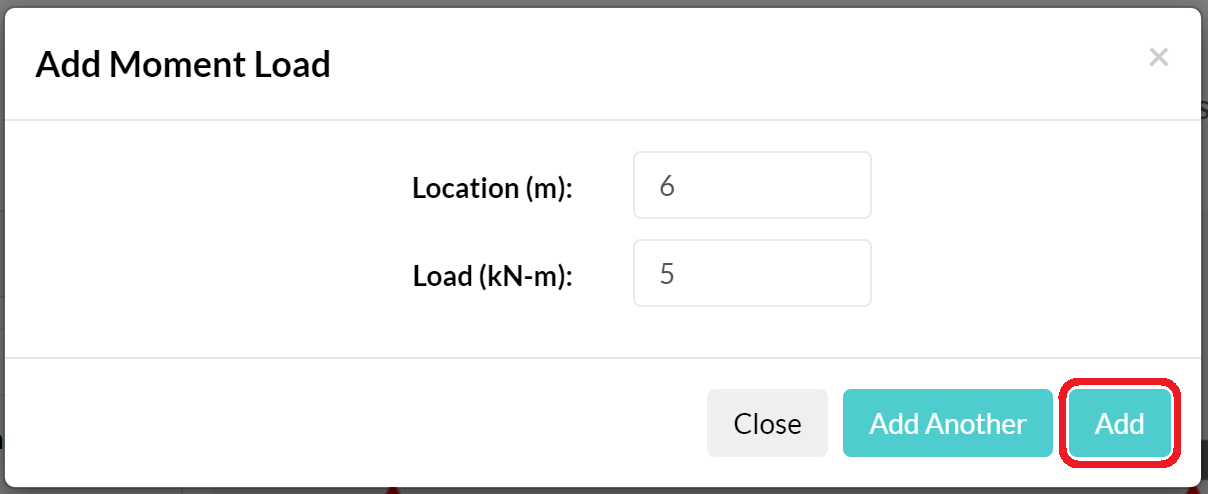
Add point, distributed, and applied-moment loads using the Beam Calculator sign convention.
- 5Assign section regions
Enter E and I for stiffness. Add A and extreme-fibre distances when the corresponding stress result is needed.
- 6Run and inspect results
Review reactions, shear, bending moment, slope, deflection, and stress. Query important locations directly.
- 7Verify, save, and report
Check equilibrium and behavior independently, then save the reviewed model and export a fresh PDF.
Read the complete Beam Calculator sign convention before entering loads or interpreting signed reactions.
When to use this workspace
One straight beam under in-plane bending
Use Beam Calculator for simply supported, cantilever, fixed, overhanging, and continuous beams with one or more section regions.
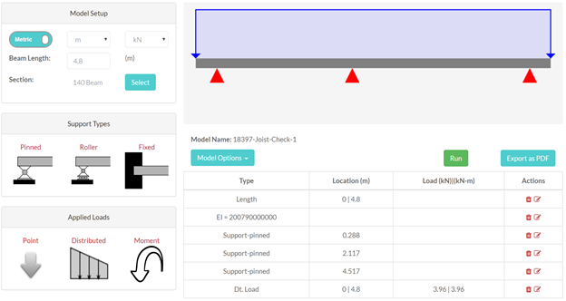
Screenshot note: These annotated guide images focus on the control locations and workflow. Minor visual details can differ as the interface is refined.
Inputs
Build the beam model
Add inputs in sequence, then use the Model Inputs and Section Properties tables to verify, edit, or remove them.
Choose the unit system
Use the Metric/Imperial switch, then choose the displayed length and force units. Imperial models start in ft and kip by default, while in and lb remain available. Section-property units appear beside each property.
- Changing working units converts existing model inputs and results; it does not only relabel them.
- Re-check every value after a switch, especially A, I, and extreme-fibre distances.
- Do not enter an imperial property while a metric label is active, or the reverse.

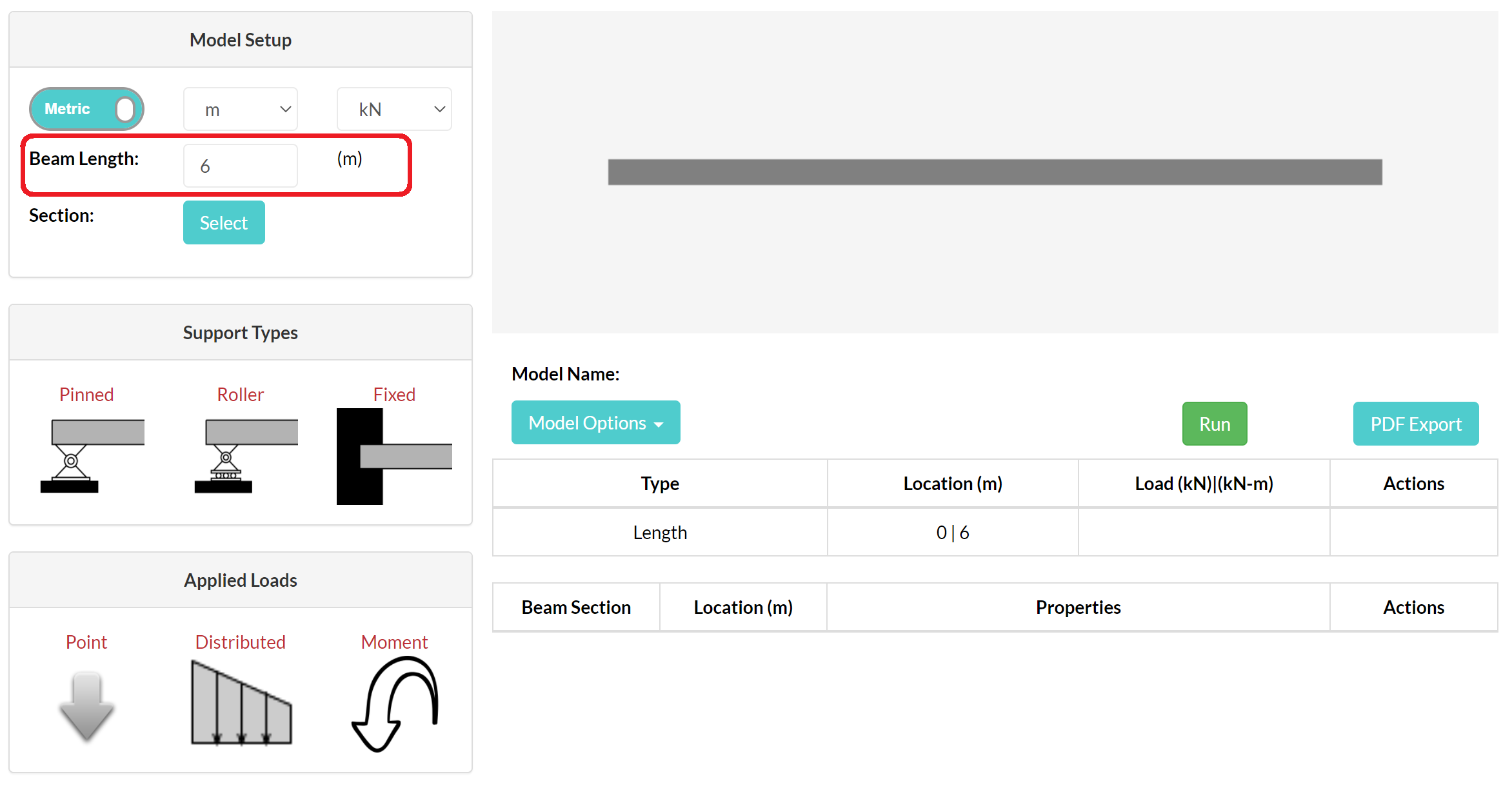
Enter the beam length
Enter a positive length and commit the field. The left end is x = 0; x increases to the right.
After shortening a beam: Supports, loads, or section limits beyond the new right end may be removed. Re-check the input tables.
Add supports
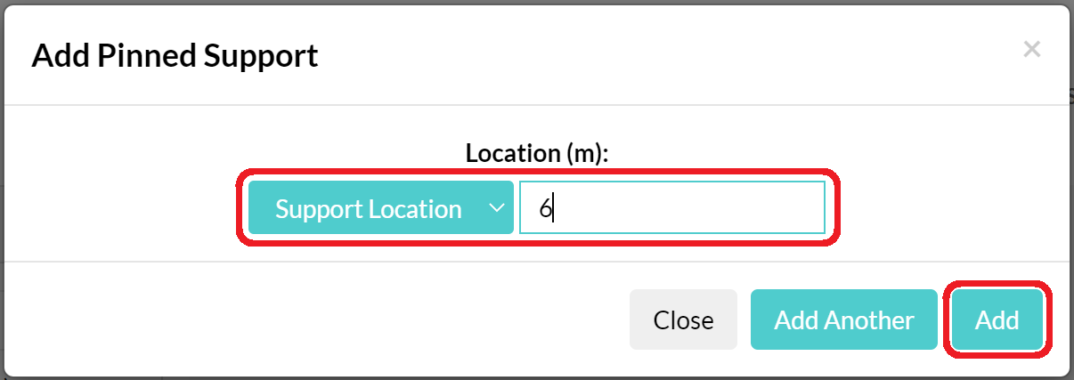
Select a support, enter its x-location, then choose Add or Add Another. Edit or delete it in the Model Inputs table. Two supports cannot occupy the same location.
Stability: The restraint pattern must prevent rigid vertical movement and uncontrolled rotation.

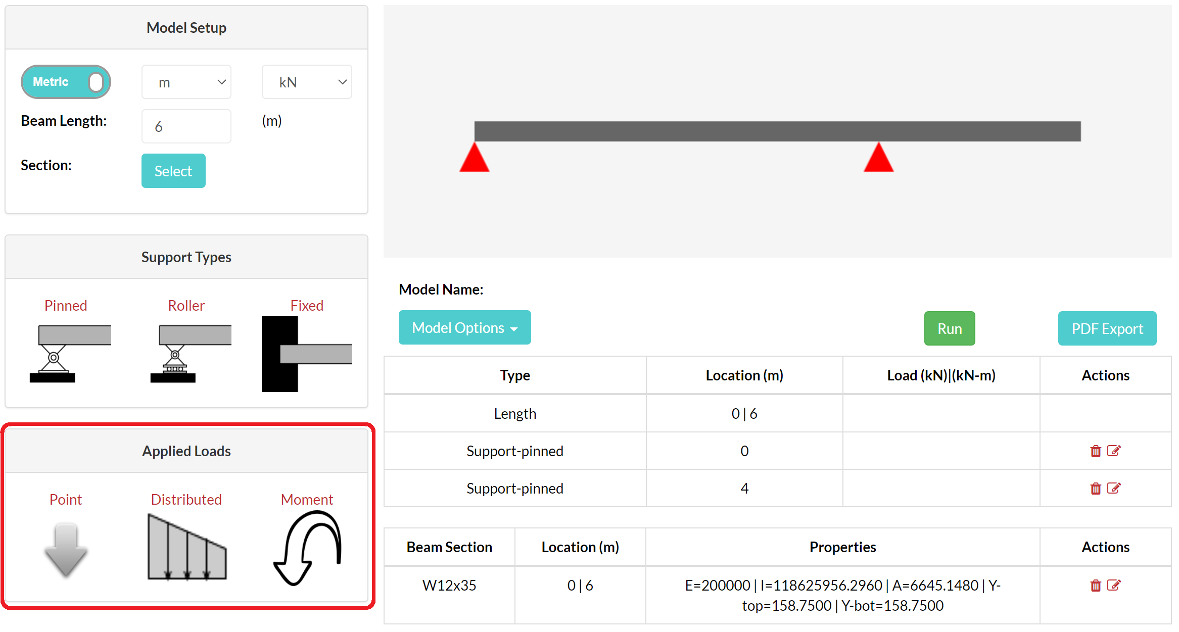
Apply loads
- Equal distributed intensities create a uniform load.
- One zero intensity creates a triangular load.
- Unequal nonzero intensities create a trapezoidal load.
- Distributed-load start and end values must act in the same direction; change both signs to reverse it.
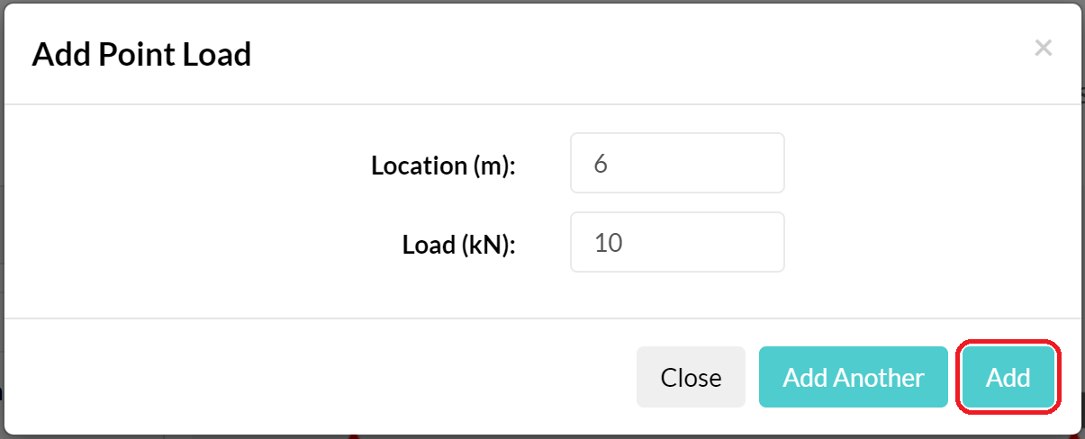
Example: Enter +8 for an 8 kN downward point load or −8 for an 8 kN upward point load.

Define section and material properties
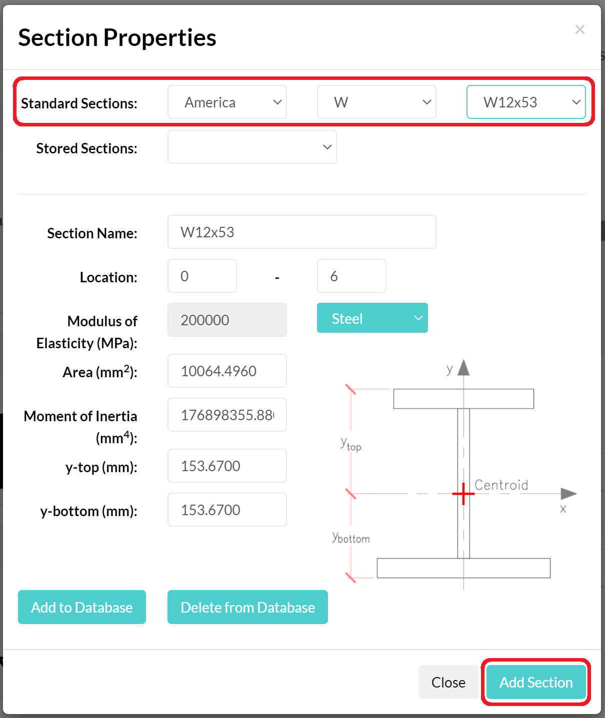
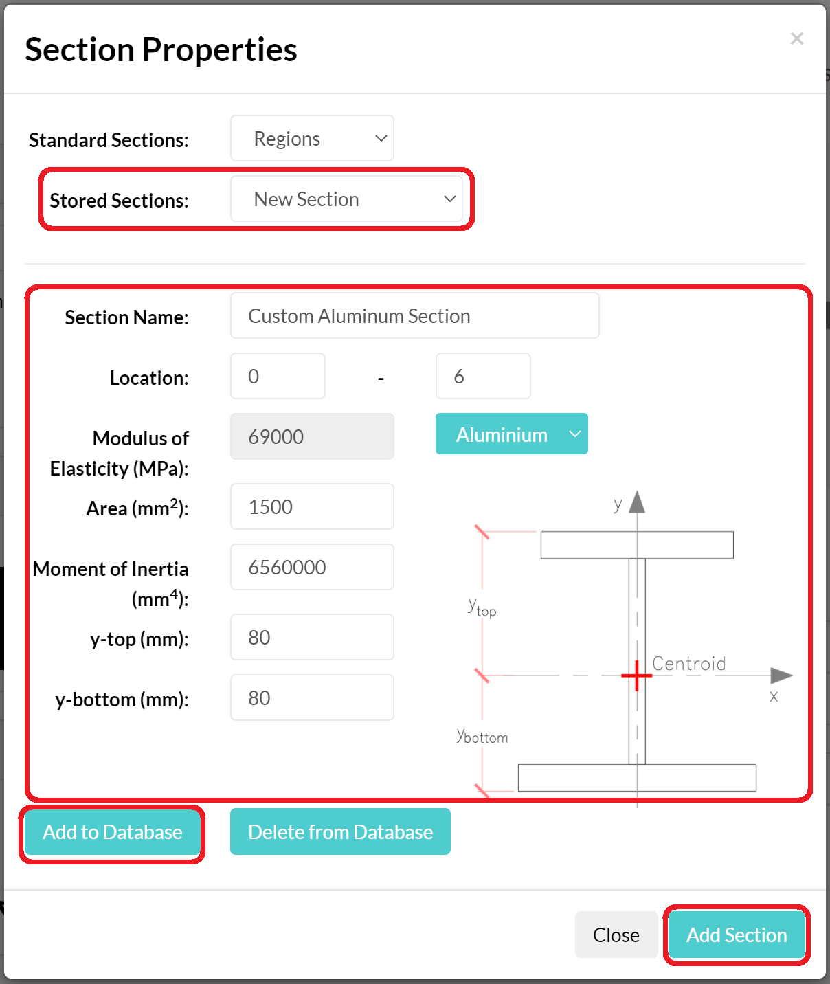
Open Section Properties. Select a standard steel section, a stored section, or New Section, then define its start and end along the beam.
| Property | Meaning | Used for |
|---|---|---|
E | Modulus of elasticity | Flexural stiffness, slope, and deflection |
I | Second moment of area about the bending axis | Flexural stiffness, slope, and deflection |
A | Cross-sectional area | Average shear-stress output |
y-top | Neutral axis to top extreme fibre | Top-fibre bending stress |
y-bottom | Neutral axis to bottom extreme fibre | Bottom-fibre bending stress |
- Section regions cannot overlap; use adjacent limits for a stepped beam.
- Cover every span region that needs stiffness, slope, deflection, or stress results.
- Confirm I and y-values use the intended bending axis.


Analyze and interpret
Run and read Beam Calculator results
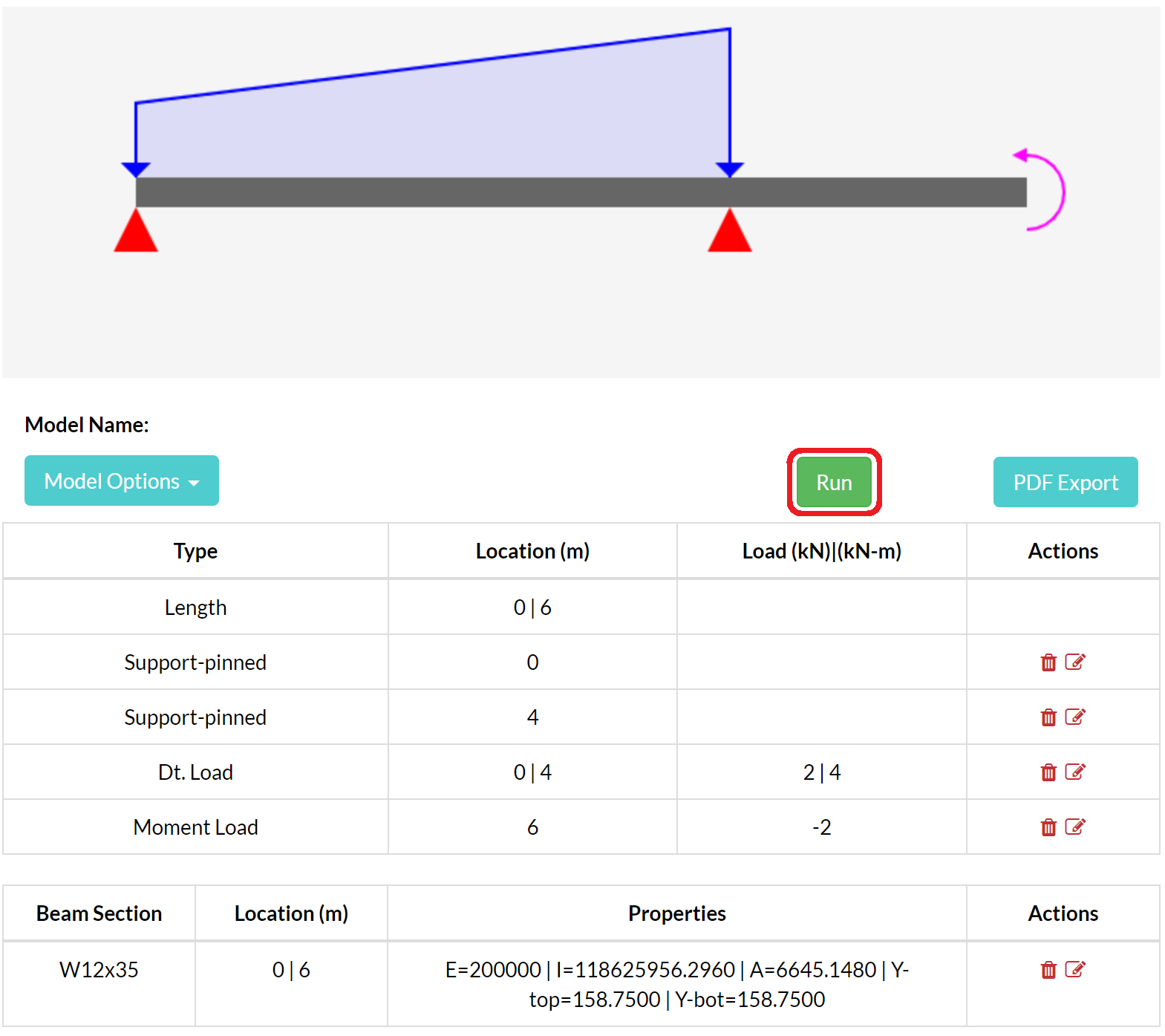
Review the input tables, select Run, and resolve any validation message before using the results.
Support reactions
Forces and fixed-end moments required for equilibrium. Keep the displayed signs when checking force and moment balance.
Shear diagram
Signed internal shear along x. Point forces create jumps; distributed loading changes the diagram slope.
Moment diagram
Positive is sagging and negative is hogging. Local moment peaks commonly occur where shear crosses zero.
Slope
Rotation of the beam centreline based on E and I. Check restrained locations, continuity, and expected symmetry.
Deflection
Transverse displacement based on flexural stiffness. Check support displacement and whether the shape matches the loading.
Stress
Bending stress uses M, I, and extreme-fibre distance. Average shear stress uses V and A and is not a detailed through-depth distribution.
Extreme-value summaries identify governing signed values; a location query is better for a support face, splice, connection, or other point of interest.







Beam Calculator reference
Sign conventions
Use this table for every signed Beam Calculator input and result.
Position x starts at the left end and increases to the right.
| Quantity | Positive (+) | Negative (−) |
|---|---|---|
| Point load | Downward | Upward |
| Distributed-load intensity | Downward | Upward |
| Applied moment | Clockwise | Counter-clockwise |
| Force reaction output | Downward | Upward |
| Moment reaction output | Clockwise | Counter-clockwise |
| Internal bending moment | Sagging | Hogging |
| Diagram ordinate | Signed positive value | Signed negative value |
The result sign follows the same convention as the load input. Retain it when checking equilibrium.
Keep a calculation record
Save, reopen, and export a beam model
Save and reopen
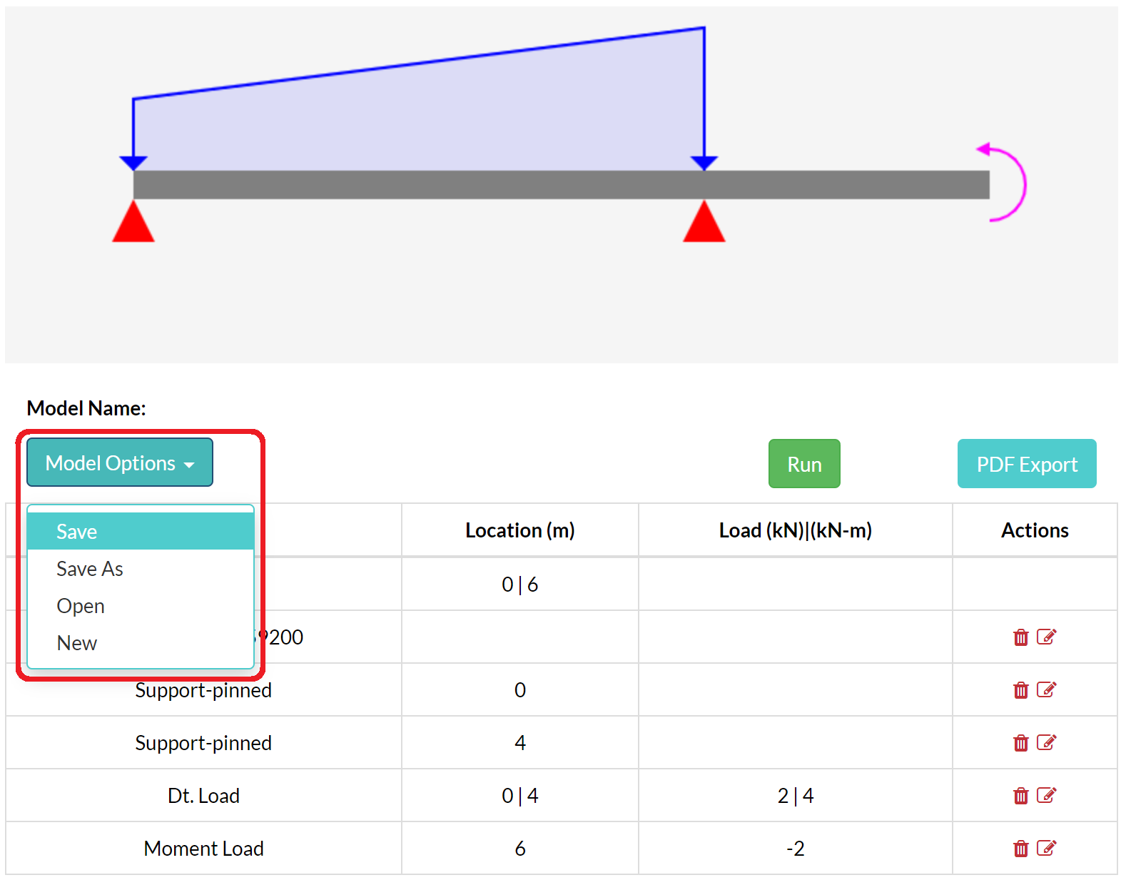
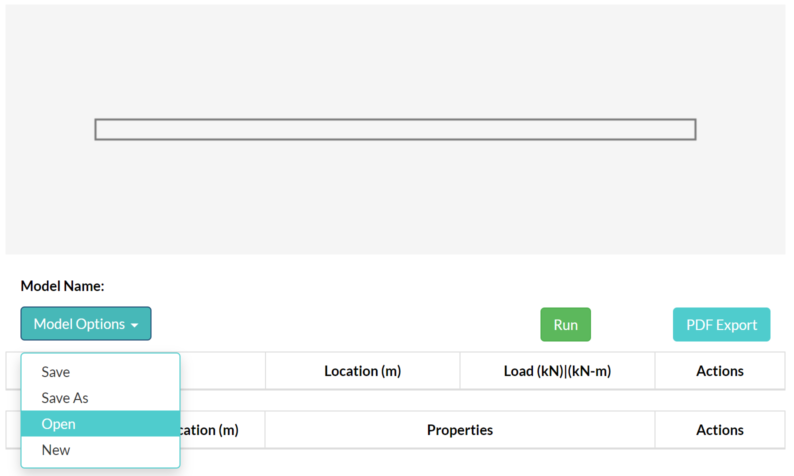
- Use Save to name a new model or update the currently open model.
- Use Save As before exploring a separate design or load variation.
- Use Open to search models and folders.
- Check the unsaved-change indicator before replacing the current model.
Saving, model counts, and folders depend on the account plan.
PDF calculation report
- Run the current model so the results are fresh.
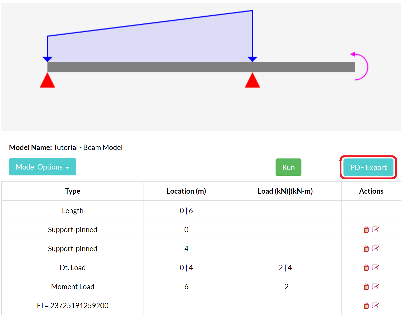
- Select PDF Export.
- Add the available project, author, notes, and branding details.
- Download and inspect every page before sharing the report.
Check that inputs, section regions, units, reactions, diagrams, assumptions, and revision information match the intended model.

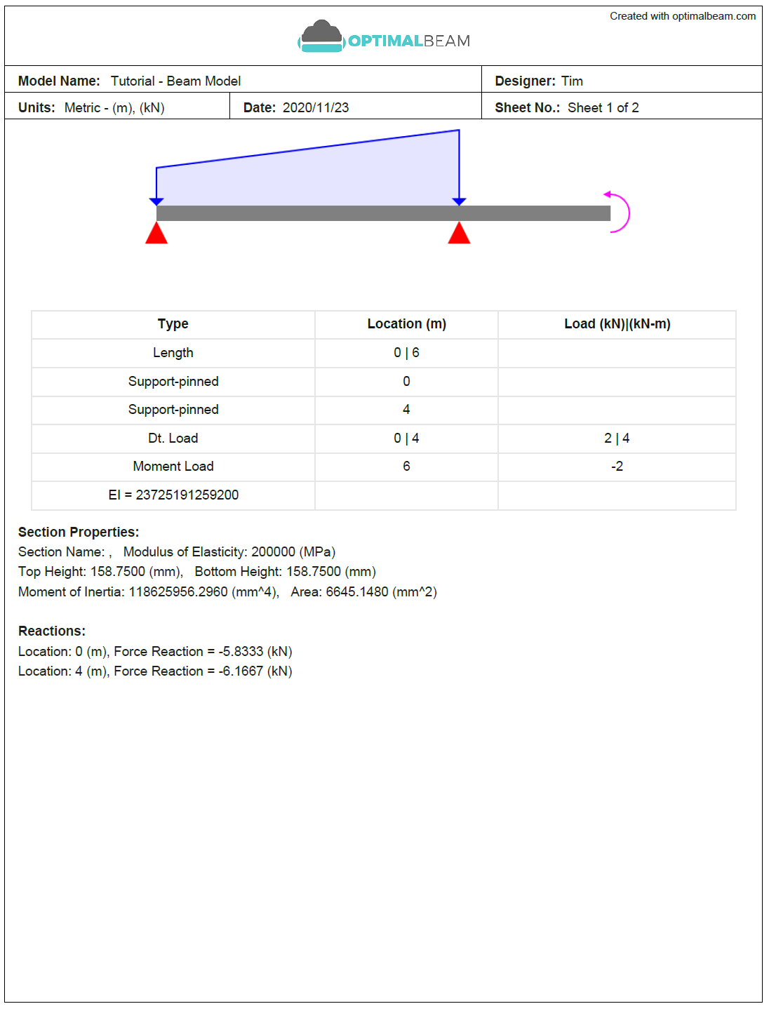
Assisted setup
Use Optimal AI as a model draft
Describe the working units, beam length, support types and locations, and every signed load. The proposed inputs can speed up setup, but section requests and generated values still require manual confirmation.
Example prompt: “Create a 6 m simply supported beam with a pin at 0 m, a roller at 6 m, and a 12 kN downward point load at 2 m.”
Review every support, location, load sign, and property in the input tables. Then run the deterministic solver and complete the normal checks.
Know the idealization
Assumptions and limits
Included
- One straight beam under in-plane, static transverse loading.
- Linear-elastic stiffness based on entered E and I.
- Ideal pinned, roller, and fixed restraints.
- Determinate and indeterminate response using stiffness-based analysis.
- Piecewise section properties along the span.
Not included
- Code resistance, load factors, or a serviceability acceptance decision.
- Connection, bearing, bracing, lateral-torsional buckling, or local-buckling design.
- Torsion, lateral loading, dynamics, construction stages, or nonlinear behavior.
- A detailed through-depth shear-flow calculation.
- Real support or connection flexibility unless represented by the idealized model.
For the calculation method, see Beam theory and the matrix stiffness method.
Before relying on results
Beam review checklist
Fix common problems
Beam Calculator troubleshooting
The beam is unstable or cannot be solved+
Confirm the support pattern prevents rigid vertical movement and rotation. Check duplicate support locations, invalid span locations, and an unintended free beam.
A load or reaction points the wrong way+
Use the Beam Calculator convention: positive force is downward, negative force is upward, positive applied moment is clockwise, and negative applied moment is counter-clockwise. A negative force reaction therefore acts upward.
Slope or deflection is missing+
Assign positive E and I over every beam region where stiffness results are needed, confirm region limits do not overlap, and run the model again.
A stress result is missing+
Bending stress needs M, I, and the relevant y-top or y-bottom distance. Average shear stress needs shear force and area A. Add the missing properties and rerun.
Results do not reflect the latest edit+
Select Run after changing length, supports, loads, or section properties. Export reports only after the latest analysis finishes.
A section region is rejected or results stop at a location+
Confirm each start is less than its end, all limits lie on the beam, and regions do not overlap. Use adjacent boundaries to describe a stepped beam and cover all required locations.
A result is many orders of magnitude too large or small+
Check E and I first. Confusing mm⁴, m⁴, and in⁴ changes flexural stiffness enormously. Also confirm load intensity units and the beam length unit.
The model cannot be saved+
Confirm you are signed in, the model has a valid name, and the current plan permits another model or revision. Use Save As only when you intend to create a separate copy.
The PDF is blank, incomplete, or fails to export+
Run the model, wait for results, and retry with default branding. Replace any invalid logo and confirm the browser allows the download. If it persists, contact support with the browser and exact error.
Quick reference
Beam symbols and terms
- x
- Location along the beam, measured from the left end.
- E
- Modulus of elasticity describing linear-elastic material stiffness.
- I
- Second moment of area about the bending axis.
- A
- Cross-sectional area.
- V
- Internal shear force.
- M
- Internal bending moment; positive sagging and negative hogging.
- Slope
- Rotation of the beam centreline.
- Deflection
- Transverse displacement of the beam centreline.
- Reaction
- Support force or moment required to satisfy equilibrium and compatibility.
- Section region
- A beam interval assigned one set of material and geometric properties.
Responsible use
Analysis supports judgment; it does not replace it.
The user remains responsible for the beam idealization, inputs, load combinations, code requirements, interpretation, independent checks, and decisions affecting safety or construction.