Back-End Development:
The back-end development consists of two components. The first component is the main C# application that implements the Matrix Stiffness Method and graphical method. The second component is PHP scripting which is used in conjunction with MySQL database that allows for a customized web application.
C# Application:
Once the user has defined their beam model by specifying all the loading conditions, boundary conditions, and beam section properties, the information is stored in a string that contains JSON, this parameter is passed to the C# application method.
First, an instance of a beam object is created from the Beam class type, then the information from the passed parameter is parsed to load a JObject using Json.net library for .NET. All the information from the JObject is then stored within the beam object which will be utilized to implement the Matrix Stiffness Method.
Nodes are then determined along the span of the beam based on the loading and boundary conditions, this allows the beam structure to be modelled into simpler elements interconnected at the nodes. The external forces acting on the newly defined nodes are calculated by finding the fixed end moment reactions based on the loading conditions, a table of common fixed end beam configurations and their reactions is presented in the appendix.
Now that the elements are identified, a stiffness matrix is computed for each element and then compiled to form the global stiffness matrix, this matrix will govern the behaviour of the overall beam model object. The creation of matrices/vectors and arithmetic operations were done utilizing Math.Net Numerics library for .NET.
The rotational and translational displacements are calculated at the nodes where displacements are permissible – when a degree of freedom exists. For example, if a node is at a pin support location, only rotational displacement may occur. The pin support does not allow translational movement of the beam model at that location, this can be seen on figure 5.
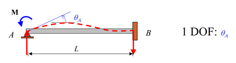
Figure 5: Degree of Freedom Example for a Pin Support [1].
By applying the force-displacement relationship, the displacements are computed by finding the inverse of the stiffness matrix at the identified degrees of freedom and multiplying it by the external reaction forces acting on the same degrees of freedom. The equation is the following:
D=K-1 x F (eq.6)
Where,
K = beam’s stiffness matrix at the degrees of freedom,
F = vector of the beam’s forces at the degrees of freedom,
At this stage, the global stiffness matrix and displacements of the beam model has been determined, the external support reaction forces can be computed by implement equation 1. The global stiffness matrix is multiplied by the displacement vector, this gives us the force reactions at the support locations.
The support reaction results are used with the boundary conditions, loading conditions, and section properties to draw diagrams that will show the variations of internal shear, internal moment, slope, deflections, bending stress, and shear stress. There are differential relations that exist as discussed in section 2.2, this gives us a graphical method to draw all the diagrams necessary for the design process of a beam.
The shear diagram points were computed by finding the internal forces in the beam.This process involves starting from the extreme left point along the beam span and moving from node to node and taking into consideration the point loads acting on the nodes. Between the nodes, there is a beam element that may experience distributed loading conditions; these distributed loads may be uniform, triangular, or trapezoidal. A definite integral is created and evaluated over the interval of the beam element. A similar process was done for the rest of the charts. Figure 6 shows shear and moment diagrams computed with Optimal Beam for a simply supported beam with a uniform distributed load.
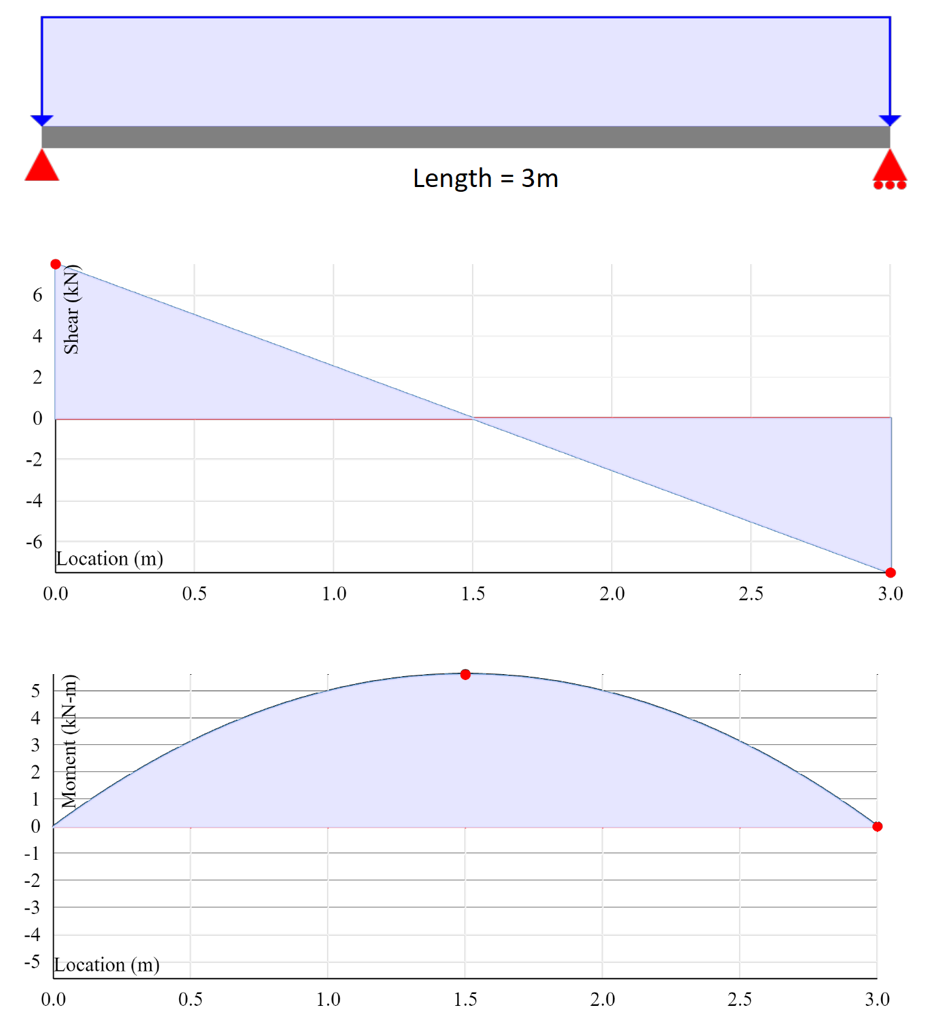
Figure 6: Optimal Beam Shear and Moment Diagram Output.
PHP Scripting:
Optimal Beam has a login and registration system, this allows customizations for each user. With the use of PHP to connect and manipulate MySQL database system, these customizations were made possible. The data is stored in different tables such as: users, statistics, models, sections, and stripe (payment). The user can choose which tier package to enroll in, each tier has differences in features and cost. Each user has unique login credentials, once logged in, they can update account information such as first name, e-mail, subscription type, cancel account, update card details, or change password.

Figure 7:Login for Optimal Beam
Figure 8:Setting form on Optimal beam
Users are also able to save beam models for future access and save commonly used sections for increased productivity. All beam data inputs for the beam model and sections are stored as a JSON string within the suitable database table.

Figure 8: Save Beam Model Feature on Optimal Beam.
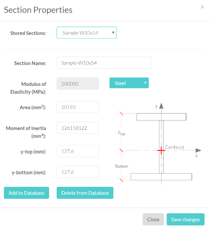
Figure 9: Section Properties Add Section to Database Feature on Optimal Beam.