Module 01 of 06
35 minutesBeam types, load paths and idealization
Compare five beam systems, select defensible supports, trace load paths and state the boundary of the model.
Suggested pacing · 35 minutes
- Illustrated systems and worked workshop15 min
- Comparison and calculation record15 min
- Knowledge check5 min
Work at your pace and record actual engaged time. Optional references and extensions may take longer.
Browse the sections in this lesson
A beam solver answers the mathematical problem it is given. The engineer’s first task is therefore not pressing Run; it is deciding which physical behaviours belong in the idealized model.
Start with the load path
Trace each load from its point of application to the supports. Record what transfers shear, what transfers axial force, and whether the connection can develop a meaningful couple. A clean sketch with dimensions and restraint directions is more valuable than an early, polished response diagram.
- Define the member centreline and analysis extent.
- Identify the restraints the surrounding structure can actually provide.
- Apply loads at their physical locations and over their real tributary lengths.
- Assign material and section stiffness consistently.
- State what the model omits before interpreting the result.
Recognize the beam system before choosing a formula
A beam type is defined by its support and continuity conditions—not by whether the member is steel, timber or concrete. The same cross-section can behave as a simple span, cantilever or continuous member depending on how it connects to the surrounding structure. That distinction controls the reaction set, bending-moment pattern and appropriate verification equations.
Guide-to-course field atlas
Five beam systems, from real structure to benchmark
Use the same sequence for every system: recognize the physical load path, assign restraints, predict the response, check a reference case, then challenge the assumption most likely to invalidate the model.
Simply supported
Determinate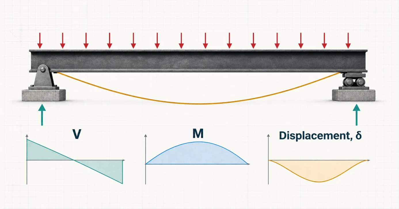
Where it appearsBridge girders on bearings, joists bearing on walls, lintels and beams with simple shear connections.
Ideal modelPin at A and roller at B. Vertical displacement is restrained at both ends; rotation remains free; one end can accommodate longitudinal movement.
Response signatureZero ideal end moments. A symmetric downward UDL produces equal reactions, positive sagging moment and a symmetric downward elastic curve.
RA = RB = wL/2
Mmax = wL2/8
δmax = 5wL4/(384EI)
Assumption to defendDo not assume “simple” merely because a connection is drawn with bolts. Confirm that connection and surrounding-frame rotational stiffness are negligible for the result being checked.
Open the complete simply supported guideCantilever
Determinate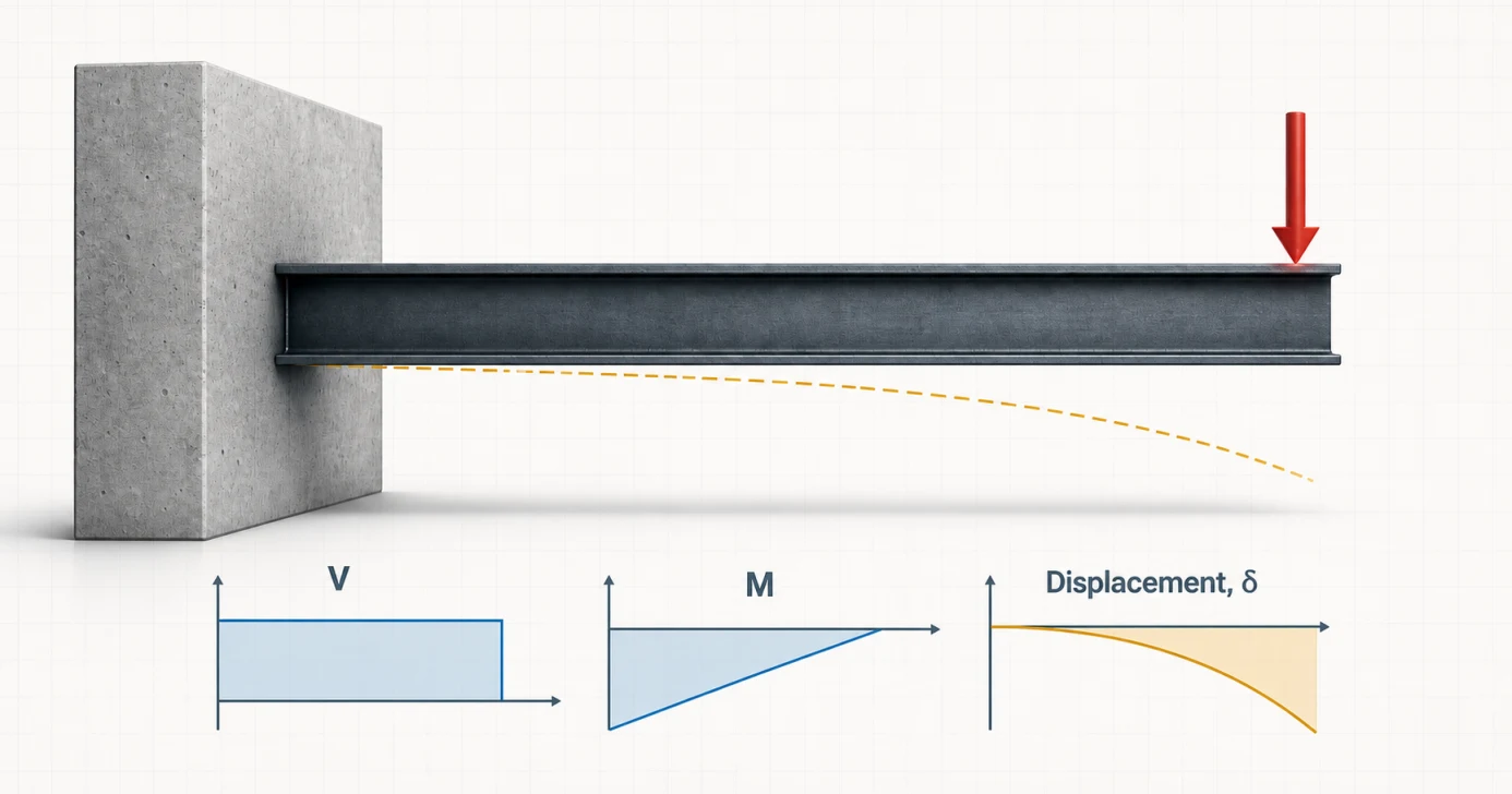
Where it appearsBalconies, entrance canopies, mast arms, brackets, retaining-wall stems and projecting roof elements.
Ideal modelOne end restrains translation and rotation; the other is free. The support must deliver shear, axial force when present and a moment couple.
Response signatureFor downward transverse loading, moment magnitude grows toward the fixity and the largest displacement normally occurs at the free tip.
VA = P
MA = −PL
δtip = PL3/(3EI)
Assumption to defendThe wall, column, base plate or foundation may rotate. A perfectly fixed symbol can seriously understate deflection when the supporting system is flexible.
Open the complete cantilever guideFixed–fixed
Indeterminate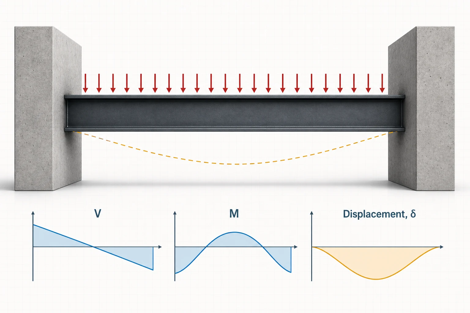
Where it appearsMonolithic concrete frames, moment-frame girders and machine members clamped by sufficiently stiff supports.
Ideal modelVertical displacement and rotation are restrained at both ends. Compatibility and EI are required to determine the end moments.
Response signatureGravity load creates hogging at the supports, sagging in the span and substantially less deflection than the equivalent simple span.
RA = RB = wL/2
MA = MB = −wL2/12
Mmid = +wL2/24
δmid = wL4/(384EI)
Assumption to defendFixity is a stiffness assumption—not a connection label. Check the joint, columns or walls, foundations and adjacent framing that must supply rotational restraint.
Open the complete fixed–fixed guideOverhanging
Usually determinate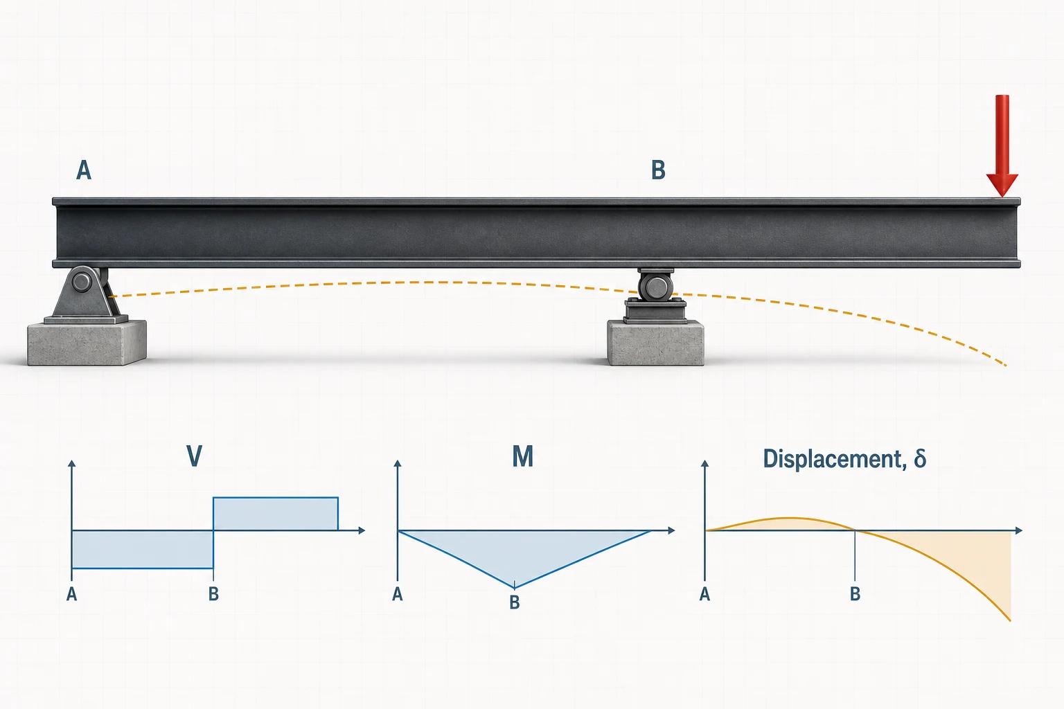
Where it appearsRoof eaves, platform edges, canopy beams and framing that projects beyond the last column or bearing.
Ideal modelA pin and roller lie inside the member length, leaving a free projection. The support span is L and the overhang length is a.
Response signatureOverhang loading creates negative moment at the inboard support and can reverse the remote reaction, demanding a real uplift load path.
RA = −Pa/L
RB = P(L+a)/L
MB = −Pa
δtip = Pa2(L+a)/(3EI)
Assumption to defendA negative reaction is not only a sign convention. Bearing-only contact cannot pull on the beam; add a hold-down, stabilizing load or a different support model.
Open the complete overhanging guideContinuous
Indeterminate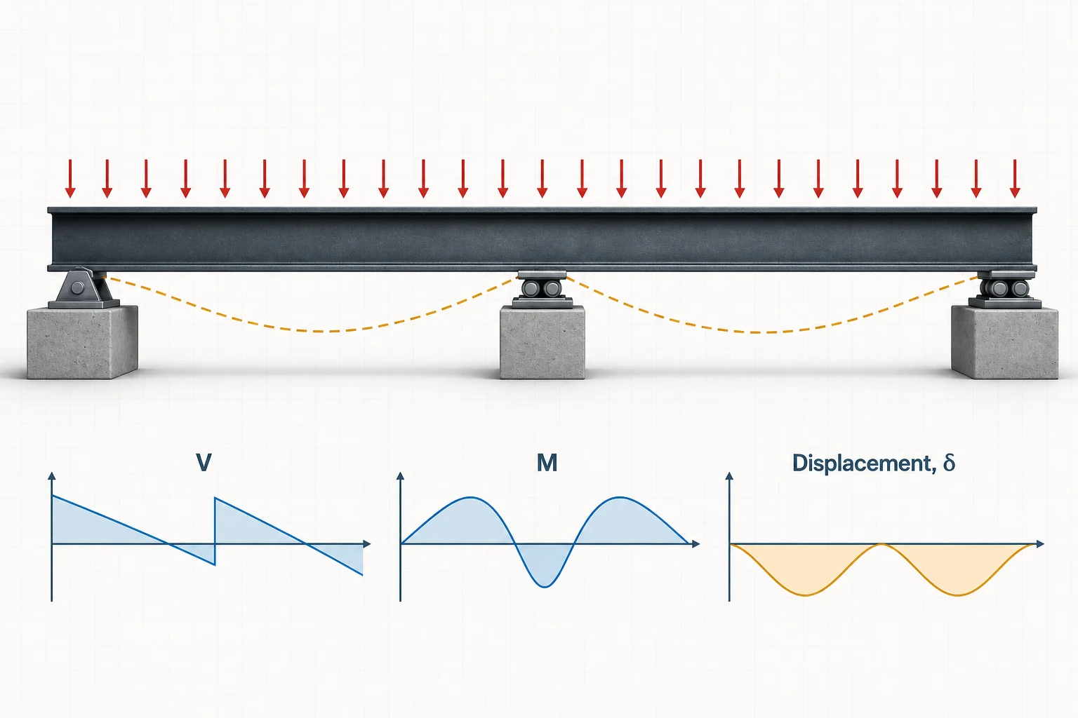
Where it appearsMulti-span bridge girders, floor beams over columns and roof purlins passing across several frames.
Ideal modelOne uncut member passes over three or more supports. Adjacent spans share rotation at an interior support, so their responses are coupled.
Response signatureContinuity creates negative interior-support moment, redistributes reactions and usually reduces balanced-load positive moment and deflection.
RA = RC = 3wℓ/8; RB = 5wℓ/4
MB = −wℓ2/8
M+max = 9wℓ2/128
Assumption to defendMembers touching at a support are not automatically continuous. Moment must pass through an uncut section or a connection capable of sustaining the required rotation compatibility.
Open the complete continuous guideHow to use the references: the equations are benchmark cases, not universal beam formulas. They are valid only for the stated geometry, loading, constant EI and boundary conditions. The dedicated guides add live diagrams, alternate load cases and full worked calculations; this course asks you to compare, predict and document the five systems in one review workflow.
Quick reference: compare the five systems
| Beam system | Idealized boundary | Determinacy and characteristic response | Typical modeling trap |
|---|---|---|---|
| Simply supported | Pin at one end, roller at the other | Statically determinate; idealized end moments are zero | Adding end fixity that the bearings or shear connections cannot provide |
| Cantilever | Fixed at one end, free at the other | Statically determinate; maximum moment commonly occurs at the fixed end | Ignoring rotation or flexibility of the supporting column, wall or base |
| Overhanging | Two supports with member extending past one or both | Usually determinate; overhang loading can reverse a reaction and create support-region hogging | Assuming a bearing can resist uplift after a reaction changes sign |
| Fixed–fixed | Rotation and translation restrained at both ends | Indeterminate; end moments reduce positive span moment and deflection | Treating nominally rigid joints as perfectly fixed without stiffness evidence |
| Continuous | One member over three or more supports | Indeterminate; continuity creates negative support moments and redistributes response | Splitting the member into independent simple spans and losing continuity |
If equilibrium supplies enough independent equations to recover the reactions, the system is statically determinate. If extra restraints introduce more unknown actions, deformation compatibility and stiffness are needed. Indeterminate does not mean “better” or “more advanced”; it means the response depends on both equilibrium and how the structure deforms.
A four-question beam-type screen
- Where can the member translate, and where can it rotate?
- Does the member continue through a support, terminate there, or project beyond it?
- Can the connection actually develop the modeled moment or uplift force?
- Would support settlement, joint flexibility or loss of contact change the load path?
Read the restraint before drawing the reaction
A support symbol is a compact statement about movement. In a two-dimensional frame model, a beam-end node can translate horizontally, translate vertically and rotate. Restraining any one of those degrees of freedom introduces the corresponding possible reaction component; whether that reaction is non-zero depends on the load case.
Degrees of freedom → reactions
Convert physical behavior into three model decisions
- 1Identify allowed movementCan the node move in x, move in y, or rotate?
- 2Mark each restraintA restraint imposes a displacement boundary condition.
- 3Draw possible reactionsRestrained translation creates force; restrained rotation creates moment.
Three common idealizations
Symbol, physical realization and model consequence
Start with what the connection lets the beam do, then add only the reaction components associated with restrained movement.
Roller support
Carries force normal to its bearing surface while allowing movement along the bearing and end rotation.
- Moves freely
- Tangential translation ut and rotation θ
- Restrains
- Normal translation un = 0
- Possible reactions
- Rn · one force normal to the surface
- Beam-end condition
- Horizontal beam end: v = 0; M = 0 if no end couple is applied
Can the physical bearing slide in the modeled direction without binding?
Modeling cautionA roller reaction is normal to the bearing surface; it is not automatically vertical.
Pinned support
Holds the beam-end node in place while allowing it to rotate without an idealized moment reaction.
- Moves freely
- Rotation θ
- Restrains
- ux = 0 and uy = 0
- Possible reactions
- Rx, Ry · two force components
- Beam-end condition
- Beam end in bending: v = 0; M = 0 if no end couple is applied
Is connection moment small enough to neglect for the result being checked?
Modeling cautionA support pin restrains a node relative to ground. An internal hinge joins members and releases transferred moment; they are not interchangeable.
Fixed support
Prevents translation and rotation, so the connection must transfer force and a moment couple into the supporting system.
- Moves freely
- No movement in the idealized 2D model
- Restrains
- ux = 0, uy = 0 and θ = 0
- Possible reactions
- Rx, Ry, M · two forces plus moment
- Beam-end condition
- Beam end: v = 0 and dv/dx = 0
Which connection, column, wall or foundation supplies the modeled moment restraint?
Modeling cautionReal connections are often semi-rigid. Perfect fixity is credible only when the complete supporting system is sufficiently stiff.
State the theory boundary
The calculator’s classical beam response assumes a small-displacement, linear-elastic idealization. The member centreline, support locations, applied loads, modulus of elasticity and section properties must be internally consistent. Local connection deformation, lateral-torsional behaviour, shear deformation, material yielding, construction sequence and load redistribution may require separate treatment.
A shear connection is modeled as fixed because the software’s default support looked convenient. The model becomes artificially stiff, end moments appear, midspan moment falls, and deflection is suppressed. The output can be numerically precise while representing the wrong structure.
Same 6 m beam. Three different answers.
Use w = 8 kN/m, E = 200 GPa and I = 200 × 106 mm4. Only the boundary conditions change. Compare physical patterns first; modules 2–4 develop the calculations.
Simply supported
Pin and roller; end rotation is free.
- Reactions
- RA = RB = 24 kN
- Moment
- Mmax = wL²/8 = 36 kN·m
- Deflection
- δmax = 3.375 mm
Fixed–fixed
End rotations are restrained.
- Reactions
- RA = RB = 24 kN
- Moments
- Mend = −24; Mmid = +12 kN·m
- Deflection
- δmid = 0.675 mm
Cantilever
One fixed end carries all actions.
- Fixed reaction
- V = 48 kN
- Moment
- Mfixed = −wL²/2 = −144 kN·m
- Deflection
- δtip = 32.4 mm
Engineering takeaway: equilibrium recovers the same 48 kN total load in all three cases, yet maximum absolute moment demand ranges from 24 kN·m (fixed–fixed) through 36 kN·m (simple span) to 144 kN·m (cantilever), and deflection from 0.675 to 32.4 mm. Selecting the wrong boundary condition can change the governing conclusion.
Five-model beam-type comparison lab
Use the comparison-and-record part of your activity plan for this lab. Before opening each model, sketch its supports, expected deflected shape and where positive or negative moment should occur. Prioritize the simple/fixed pair, then check the other systems. The goal is a mental library of response patterns, not memorizing isolated maximum values; record any additional study time.
| Prepared system | Prediction to write first | Open model |
|---|---|---|
| 6 m simple span, 8 kN/m UDL | Equal reactions; zero end moment; symmetric positive moment and downward deflection | Simply supported model → |
| 3 m cantilever, 24 kN tip load | 24 kN base shear; 72 kN·m base moment; largest deflection at the free tip | Cantilever model → |
| 6 m fixed–fixed beam, 8 kN/m UDL | Equal reactions; negative end moments; smaller positive span moment and deflection than the simple span | Fixed–fixed model → |
| Two-span continuous beam, 8 kN/m UDL | Negative moment over the centre support and positive moment in both spans | Continuous model → |
| 6 m span + 2 m overhang with tip load | Possible uplift at A; large negative moment at B; largest movement near the free tip | Overhanging model → |
- Verify the supports, span dimensions and loading before looking at any result.
- For each system, mark the reaction directions and all locations where moment must be zero or where rotation is restrained.
- Compare the simple and fixed–fixed UDL cases. Both carry 48 kN total, but their moment and deflection patterns differ because their boundary conditions differ.
- Compare the continuous and overhanging cases at the inboard support. Explain why both can show negative moment while the physical mechanisms are different.
- Identify which two models cannot be solved completely by equilibrium alone and name the compatibility information the solver must enforce.
Reveal the comparison reference
The simple span and cantilever are determinate. The fixed–fixed and continuous models are indeterminate and require stiffness plus compatibility. The overhang is determinate but can demand uplift restraint. For the symmetric UDL cases, the simple-span maximum moment is wL²/8 = 36 kN·m. The fixed–fixed reference has end moments of magnitude wL²/12 = 24 kN·m and positive midspan moment of magnitude wL²/24 = 12 kN·m. The reduction is a consequence of rotational restraint, not a change in applied load.
Create a five-row comparison table with beam type, determinacy, expected reaction pattern, moment boundary conditions, deflected-shape description and one physical assumption that could invalidate the model. This is the principal activity for the 35-minute module.
Practice: write the model statement
Choose a real beam from your work or studies and write one sentence for each item: analysis extent, supports, loads, stiffness, expected response and excluded behaviours. Challenge each support with the question “what surrounding component supplies this restraint?” This six-line record is the beginning of your calculation audit trail.
Workshop 1 · From a detail to an analysis decision
What must be true for your support symbol to be credible?
A project sketch labels a beam “supported by a steel column.” That description tells you where the force goes, but does not establish rotational restraint. A seat, shear tab, end plate and welded moment connection can all connect a beam to a column and produce different behaviour. Begin with the connection detail and the stiffness of everything behind it. A strong connection attached to a flexible column does not create an infinitely rigid boundary.
For this exercise, picture a 6 m floor beam carrying a uniformly distributed 8 kN/m service load. Its left bearing locates the member horizontally; the right bearing can slide. Both bearings allow rotation. The idealization is a pin and roller. Label A and B at the actual bearing centrelines, and identify which member length belongs in the calculation. A beam that physically extends beyond the bearings has an overhang even if the drafting label says “simple beam.”
Worked decision: a credible simple support
- State the observed detail. Both ends transmit vertical shear. No designed moment couple or significant rotational stiffness is established. One bearing accommodates axial movement.
- Translate it into conditions. At A: u = 0 and v = 0. At B: v = 0. Neither support imposes θ = 0. For this load case, axial reaction is zero, although the pin could carry horizontal force under another load.
- Predict before calculating. Under a symmetric UDL, both reactions are upward and equal, bending is sagging, end moment is zero, and downward deflection peaks at midspan.
- Calculate a benchmark. R = 8(6)/2 = 24 kN. Mmax = 8(6²)/8 = 36 kN·m. A fixed–fixed calculation produces the same vertical reactions, so equilibrium alone cannot choose between the models.
- Identify evidence that could change the decision. Obtain the actual connection and bearing details. If they establish meaningful restraint, compare a justified stiffness model with the simple-span benchmark and document the sensitivity.
Stability and determinacy are separate checks
For a planar rigid body, three independent equilibrium equations are available. A conventional pin plus horizontal roller supplies three appropriately arranged restraints. Replacing the pin with a second horizontal roller leaves horizontal rigid-body translation unrestrained. Adding restraints may make the system indeterminate, but counting reaction components alone is not a proof of stability: their directions and locations matter.
A model can also become unstable when a support loses contact. A roller symbol that permits a downward reaction implicitly represents a device capable of pulling on the member. A plain bearing cannot do that. The capstone will deliberately expose this difference. Treat stability as a property of the member, restraints and load case together.
Predict the consequences of continuity
Now imagine the same physical member continues across a middle support. An uncut section enforces displacement and rotation compatibility across that location. The support can have zero external moment reaction while the continuous beam has a non-zero internal bending moment there. “Roller support” does not mean “internal hinge.” Inserting a hinge releases moment transfer; splitting the beam into separate spans changes the structure being solved.
“Analyze the 6 m centreline span as a prismatic Euler–Bernoulli beam with constant EI, small displacements and linear elastic response. Use a pin at A and a vertical roller at B, justified by rotating bearings with axial movement at B. Apply the stated 8 kN/m service load once. Exclude connection deformation, lateral stability and member resistance from this calculation.”
Your decision exercise
Use the three-boundary comparison above to calculate the required values in the activity record. Your explanation should say what detail would justify fixing the ends, what effect that would have on moments and displacement, and what would remain unchecked. Write the statement before inspecting the reference wording. This is the first entry in your saved calculation workbook.
Optional extension · A spring between pin and fixed
A real joint can be represented by a rotational spring with stiffness kθ. Comparing kθ with EI/L helps identify whether joint rotation is likely to matter; the ratio kθL/EI is dimensionless. A low ratio approaches a released rotation, and a high ratio approaches rotational restraint. Neither limit supplies a universal cutoff: choose a model whose sensitivity is acceptable for the actual decision. Investigate this only after completing the core comparison; extra study time is recorded separately from the planned activity budget.
Required calculation record · Module 1
Defend a support model
A 6 m floor beam carries 8 kN/m. Draw a pin at A and roller at B, then compare with an ideal fixed–fixed model. Use the full-span UDL benchmarks above.
Use a calculator and your notes. Enter numbers in the stated units, without unit text or thousands separators. Your calculations receive numerical feedback; your written reasoning is retained in the workbook and is not individually instructor-graded.
This is the exercise included in the free preview. Work it on paper; enrollment adds a study-time log, saved calculation records and a certificate after successful course completion.
Continue the course
Work toward your hours and completion certificate.
$99 USD, paid once. Follow the 3-hour CPD / PDH learning plan, record your actual study time and receive your personalized certificate after completing the activities and passing the assessment.
See pricing and enrollment